
System and method for thermal transfer print head profiling

a technology of thermal transfer and print head, applied in the field of thermal transfer printing, can solve the problems of varying thermal response, not having identical characteristics of print head, and exceeding the expertise level of most end users

Inactive Publication Date: 2008-05-13
HAND HELD PRODS
View PDF37 Cites 20 Cited by
  • Summary
  • Abstract
  • Description
  • Claims
  • Application Information

AI Technical Summary

Benefits of technology

The patent describes a system and method for thermal transfer print head profiling. The print head includes a housing, resistive heating elements, and a print head memory with two memory regions. The printing profile includes information about the resistive heating elements and their operation, while the usage data includes information about the print head's usage. The print head memory stores the printing profile and the identification data that identifies it as authorized for use in the printer. The system includes a thermal transfer printer with a control assembly and a print head installable in the printer. The print head receives electrical energy from the printer and has adjustable thermal output. The system also includes a print head memory with two memory regions that store the printing profile and the identification data. The technical effects of this patent include improved print quality and tracking of print head usage.

Problems solved by technology

This lack of interchangeability is due to printer design and operating parameters, which allow for print heads to be specifically tailored to a particular printer.
However, imperfections during manufacture actually produce print heads that do not have identical characteristics and as a result have varying thermal responses.
This is beyond the expertise level of most end users.
In addition, it requires a significant amount of time to create such a profile.

Method used


Image

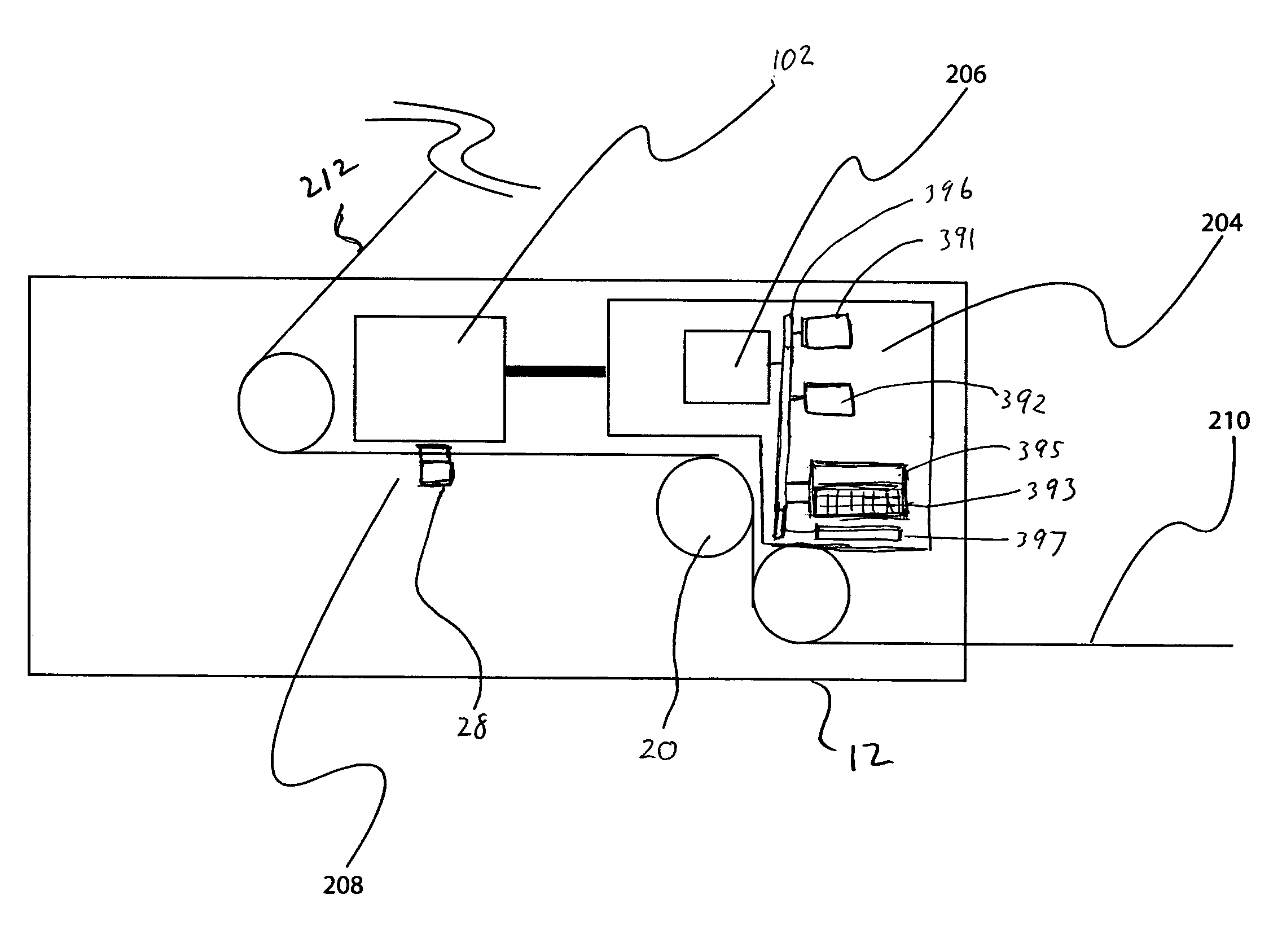
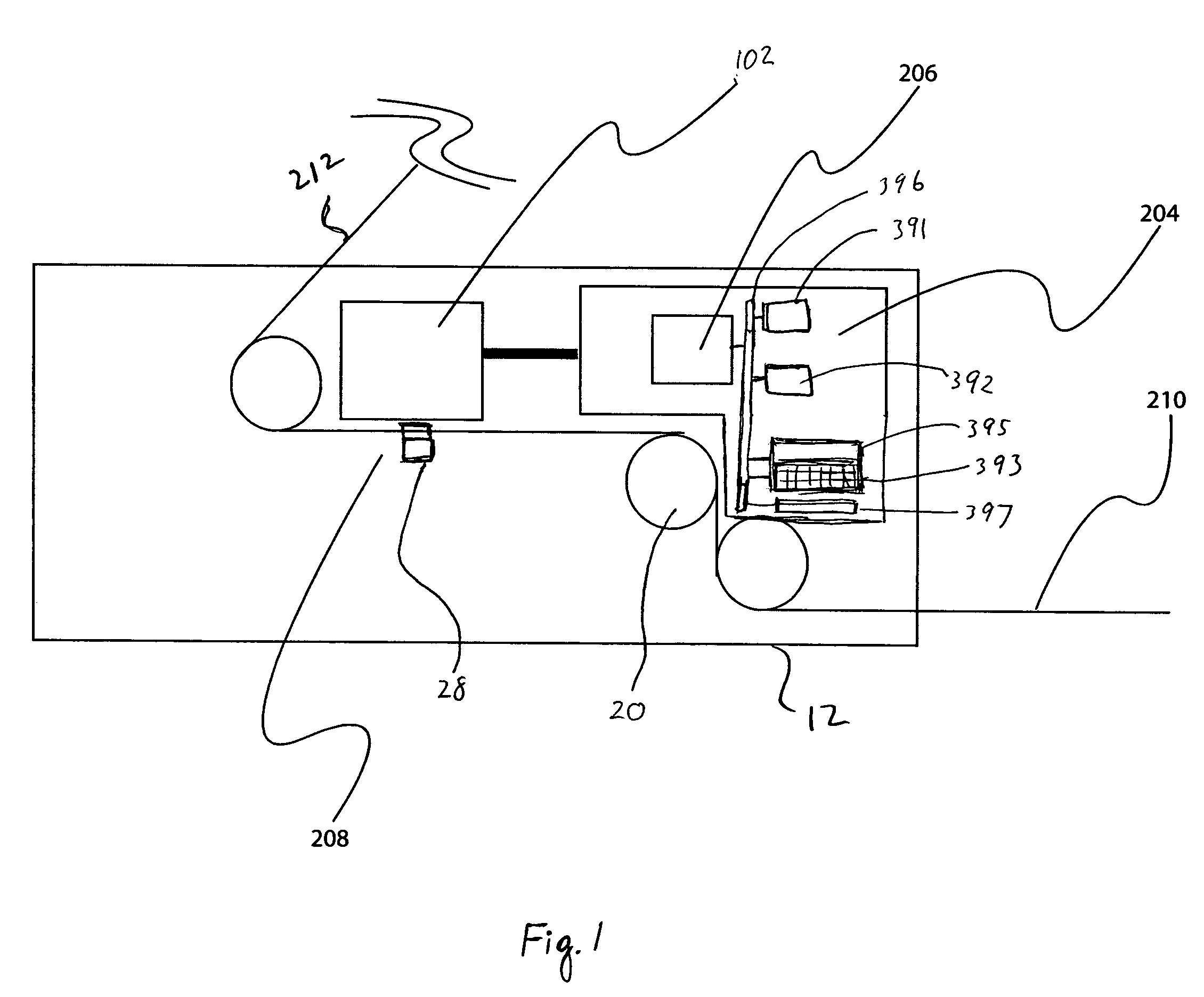
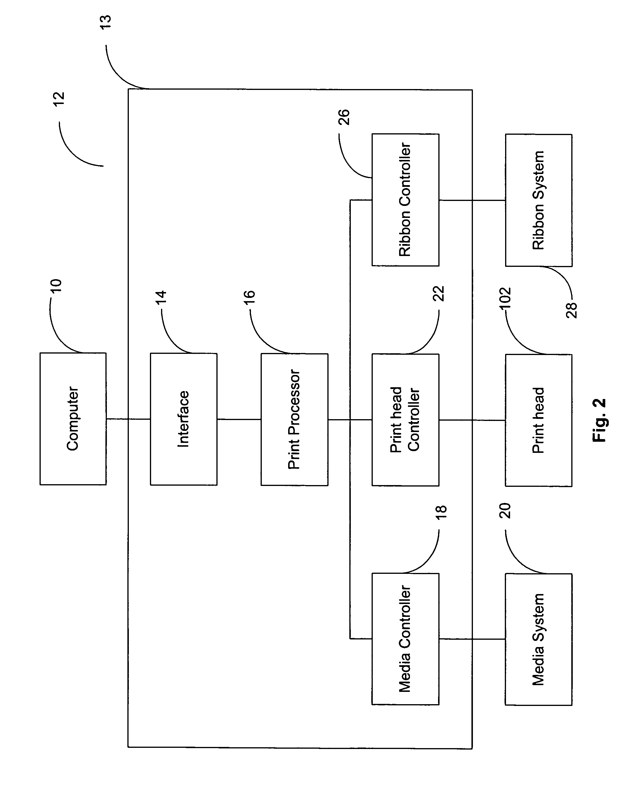
  • System and method for thermal transfer print head profiling
  • System and method for thermal transfer print head profiling
  • System and method for thermal transfer print head profiling

Examples


Embodiment Construction

[0018]Preferred embodiments of the present disclosure will be described herein below with reference to the accompanying drawings. In the following description, well-known functions or constructions are not described in detail to avoid obscuring the present disclosure in unnecessary detail.

[0019]The present disclosure provides for a system and method of profiling a thermal print head. The print head is configured to electrically connect to a thermal transfer printer and heat dyes deposited on a thermal transfer ribbon to transfer them to print media using resistive heating elements. The print head includes memory configured to store a printing profile and usage data. The printing profile includes information pertaining to the resistance of the heating elements which are used by the printer to adjust its current to achieve better printing quality. In addition, the usage data is extracted and analyzed to determine the cause of any problems and general usage statistics.

[0020]It should b...


PUM


Abstract

A thermal transfer print head is disclosed. The print head includes a housing configured and dimensioned to be installable within the printer, a plurality of resistive heating elements positioned on an external surface of the housing and in thermal contact with a printable media, the resistive heating elements receive electrical energy from the printer and have adjustable thermal output, and a print head memory positioned within the housing and accessible by the thermal printer, the print head memory including a first and second memory regions, the first memory region configured to store a printing profile pertaining to operating parameters of the resistive heating elements and the second memory configured to store usage data pertaining to operation of the print head.

Description

BACKGROUND[0001]1. Field of the Disclosure[0002]The present disclosure relates to thermal transfer printing, more specifically, to a system and method for print head profiling in a thermal transfer printer and storing usage data pertaining to the print head therein.[0003]2. Description of the Related Art[0004]Currently, there are a variety of printing techniques to transfer ink or toner to a sheet of paper, such as liquid and solid ink printing, toner laser printing, dye-sublimation printing and thermal transfer printing. In the case of thermal printing, a thermal print head provides thermal energy to specific locations of thermal-reactive printing media such as a thermal transfer ribbon. Generally, a thermal print head has a plurality of independently controllable resistive heating elements, when activated, heat a transfer ribbon and transfer thermally reactive inks or dyes from the ribbon to the paper. During this process, the heating elements cause the ink in discrete regions of ...

Claims


Application Information

Patent Timeline
Patent Type & Authority Patents(United States)
IPC IPC(8): B41J2/32
CPCB41J2/325B41J2/355
Inventor VAZAC, GEORGESCHWALLIE, RONALD A.COLONEL, KENNETH
Owner HAND HELD PRODS
Learn More