Degauss waveform generator for perpendicular recording write head

a write head and degauss waveform technology, applied in the field of degauss waveform generator for perpendicular recording write head, can solve the problems of many high-frequency components, which constitute peak current waveforms, and can not be promptly and properly degaussed, and the actual peak current can chang

Inactive Publication Date: 2008-05-13
HITACHI GLOBAL STORAGE TECH NETHERLANDS BV
View PDF17 Cites 16 Cited by
  • Summary
  • Abstract
  • Description
  • Claims
  • Application Information

AI Technical Summary

Benefits of technology

[0034]According to a first aspect of the present invention, there is provided a hard disk drive, which includes a magnetic recording medium and a write head for writing data onto the magnetic recording medium, wherein the polarity of a current flowing to the write head is reversed in accordance with the data to write the data onto the magnetic recording medium. The hard disk drive comprises: a first current source for supplying a first current, which flows to the write head, in order to write the data onto the magnetic recording medium; a second current source for supplying a second current, which flows to the write head, when the polarity of the first current changes; a switching circuit for reversing the polarities of currents flowing from the first and second current sources to the write head; and a control circuit for exercising control after the data is completely written so that the second current, which flows from the second current source to the write head when the polarity of the first current is reversed, becomes approximately zero before the first current converges to approximately zero during a degauss period during which the write head is degaussed by flowing the first current to the write head with the polarity of the first current reversed while the first current is attenuated. Consequently, the hard disk drive according to the first aspect of the present invention may degauss the write head promptly and properly.
[0048]The present invention provides a hard disk drive that is capable of performing degaussing promptly and properly.

Problems solved by technology

However, many high-frequency components, which constitute a peak current waveform, are likely to vary under the influence of write head inductance and parasitic capacitance.
Consequently, degaussing cannot be performed promptly and properly due to a disordered degauss current waveform, which causes the actual peak current to change.
If such setup is directly applied to the degauss current waveform, the current cannot smoothly attenuate to zero.
As a result, degaussing cannot properly be performed in the conventional HDD.

Method used


Image

  • Degauss waveform generator for perpendicular recording write head
  • Degauss waveform generator for perpendicular recording write head
  • Degauss waveform generator for perpendicular recording write head

Examples


first embodiment

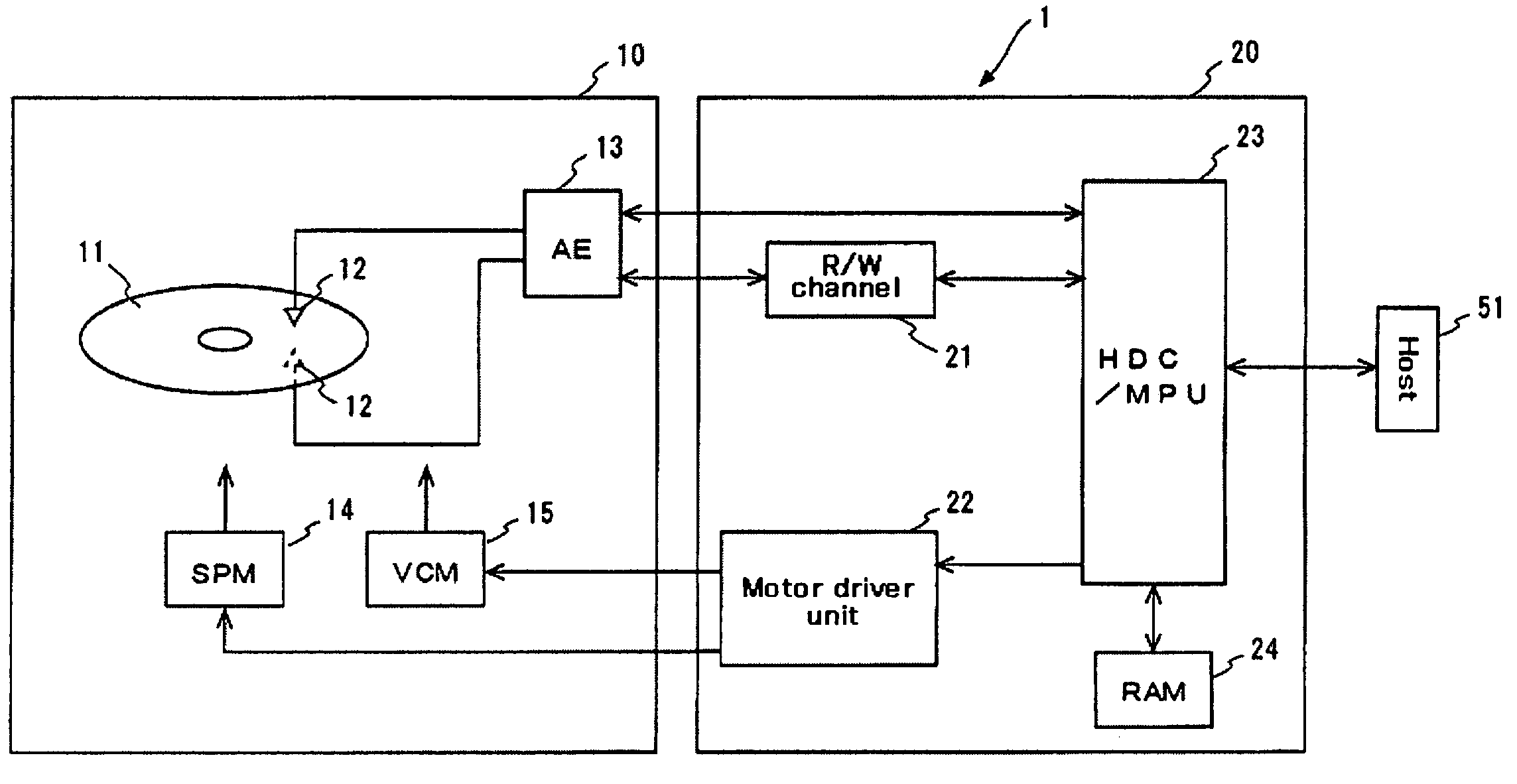
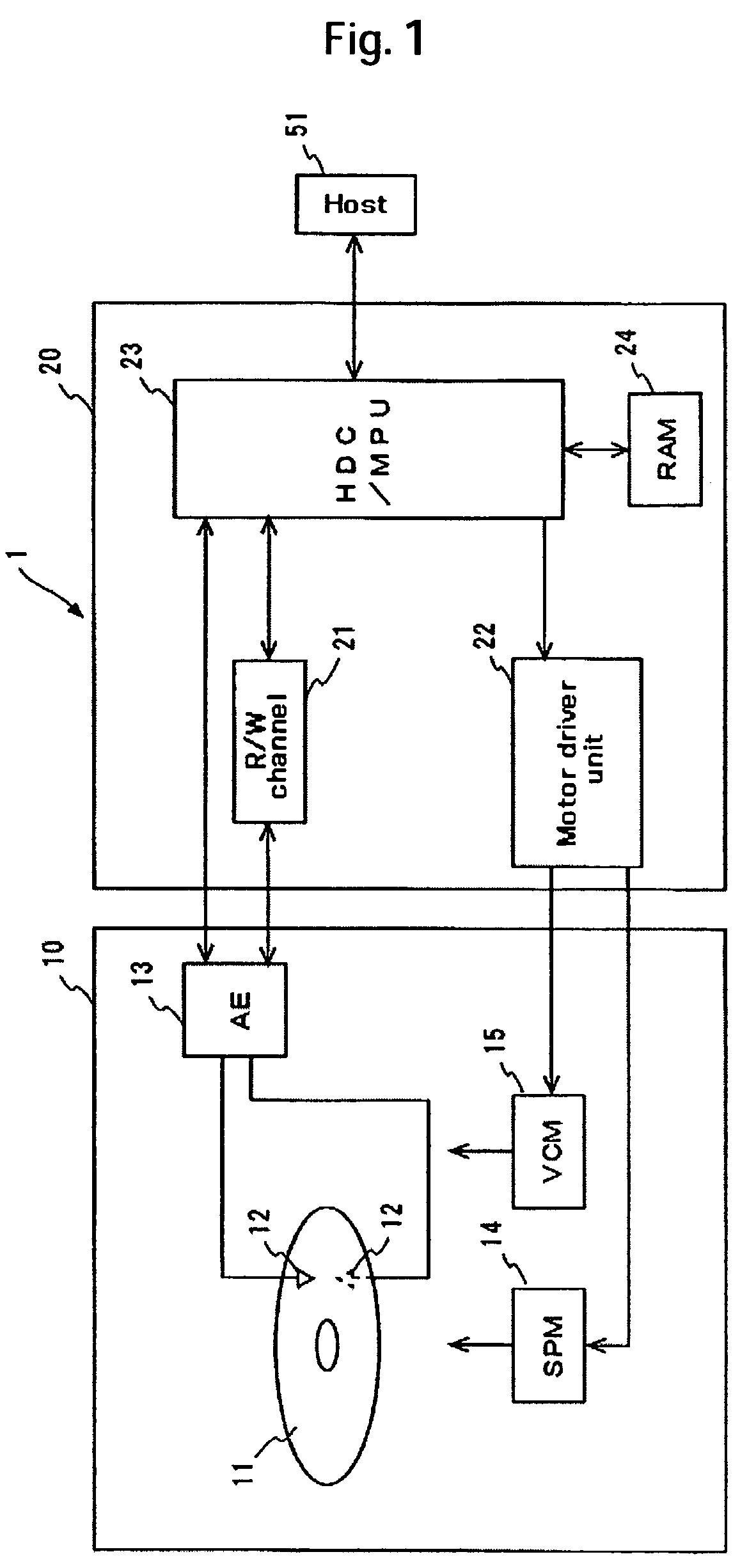
[0058]A first embodiment of the present invention will now be described in detail with reference to the accompanying drawings. For ease of understanding of the present invention, the overall configuration of a hard disk drive (HDD), which is an example of a recording media drive, will be first outlined. FIG. 1 is a block diagram that schematically shows the configuration of an HDD 1 according to the present embodiment. The HDD 1 comprises a magnetic disk 11, which is a typical recording medium, a head element section 12, which is a typical head, an arm electronic circuit (arm electronics or AE) 13, a spindle motor (SPM) 14, and a voice coil motor (VCM) 15. These components are positioned within a hermetically sealed enclosure 10.

[0059]The HDD 1 includes a circuit board 20, which is fastened to the outer surface of the enclosure 10. Mounted on the circuit board 20 are a read / write channel (R / W channel) 21, a motor driver unit 22, an integrated circuit incorporating a hard disk contro...

second embodiment

[0098]An HDD according to a second embodiment will now be described with reference to FIG. 5. FIG. 5 shows the configuration of a part of the AE. The basic configuration of the HDD according to the present embodiment will not be described because it is the same as that of the HDD according to the first embodiment. Further, the control process performed during the normal write period will not be described because it is the same as in the first embodiment. In the first embodiment, the current flowing from the current source 166 to the write head 150 is controlled in accordance with an on / off operation of the switch 164. In the present embodiment, however, the current I2 supplied from the current source 166 is controlled in accordance with a register value that is stored in a register 143 for the AE 13.

[0099]In the present embodiment, the output from the single shot (S / S) 141 directly enters the switch 164, which is shown in FIG. 3. This ensures that the switch 164 turns on during the ...


PUM

PropertyMeasurementUnit
write currentaaaaaaaaaa
currentaaaaaaaaaa
currentaaaaaaaaaa

Abstract

Embodiments of the invention provide a hard disk drive that is capable of performing degaussing promptly and properly and a recording method for use with such a hard disk drive. A hard disk drive according to one embodiment of the present invention comprises a current source for supplying a first current, which flows to a write head for writing data onto a magnetic disk; a current source for supplying a second current, which flows to the write head when the polarity of the first current changes; transistors for reversing the polarity of a current flowing to the write head; and a control circuit for exercising control so that the second current I2, which flows from the current source to the write head when the polarity of the first current I1 is reversed, becomes approximately zero before the first current I1 converges to approximately zero during a degauss period.

Description

CROSS-REFERENCES TO RELATED APPLICATIONS[0001]This application claims priority from Japanese Patent Application No. JP2005-007659, filed Jan. 14, 2005, the entire disclosure of which is incorporated herein by reference.BACKGROUND OF THE INVENTION[0002]The present invention relates to a hard disk drive and recording method, and more particularly to a hard disk drive that degausses a write head and a recording method for use with such a hard disk drive.[0003]Information read / write devices using various types of media such as optical disks and magnetic tapes are known in the art. Among them, hard disk drives (hereinafter referred to as HDDs) have become popular as storage devices for computers to such an extent that they are one type of the storage devices indispensable for today's computers. Further, not limited to computer systems, HDDs are expanding more and more in application because of its excellent characteristics. For example, HDDs are used for moving picture read / write devices...

Claims


Application Information

Patent Timeline
Patent Type & Authority Patents(United States)
IPC IPC(8): G11B5/03
CPCG11B5/1278G11B5/465E01D19/086E01D19/125
Inventor SUZUKI, HIROAKIOKADA, KENJI
Owner HITACHI GLOBAL STORAGE TECH NETHERLANDS BV
Why Eureka
Try Eureka