Method and apparatus for allocating channelization codes for wireless communications

a wireless communication and channelization code technology, applied in the field of communication systems, can solve the problems of inefficient use of limited channel resources, reduced efficiency of channel resources, and other links being considered extremely bad, and achieve the effect of enhancing the capability of symbol detection of the receiving end

Inactive Publication Date: 2008-05-13
LG ELECTRONICS INC
View PDF6 Cites 96 Cited by
  • Summary
  • Abstract
  • Description
  • Claims
  • Application Information

AI Technical Summary

Benefits of technology

[0066]Therefore, a first object of the present invention is to provide an apparatus and method for allocating channelization codes in a mobile communication system capable of enhancing a symbol detection capability of a receiving end.
[0067]A second object of the present invention is to provide an apparatus and method for allocating channelization codes in a mobile communication system capable of improving usage efficiency of a limited channel resource.
[0069]A fourth object of the present invention is to provide an apparatus and method for allocating channelization codes in a mobile communication system capable of increasing a throughput of data that can be sent through channelization codes.
[0072]The inventors have recognized and addressed at least the above-explained shortcomings of the related art by developing a technique for improved symbol detection performance at the receive end of a MIMO system when allocating channelization codes in a mobile (wireless) communication system. As a result, the efficiency of using channel resources can be improved, data throughput can be increased, and channelization codes can be shared between users according to the transmit antennas.
[0075]Also, the inventors recognized and addressed the problems of the related art by developing a signal transmitting method for a MIMO system in which channelization codes are shared by multiple terminals when the number of terminals is greater than the number of channelization codes, such that radio resources are more efficiently utilized.

Problems solved by technology

Thus, even if the link quality between the base station and the terminals is considered to be good, in actuality, certain links may be considered extremely good while other links may be considered extremely bad.
However, if the total number of channelization codes is less than the total number of users, and the related art channelization code allocation method is employed, there are situations where limited channel resources cannot be efficiently used.
Namely, as shown in FIG. 4, when there are eight users and four channelization codes are used, certain terminals (i.e., UE2, UE4, UE5, and UE6) are not allocated with any channelization codes, and thus the efficiency of using channel resources is undesirably decreased.
Additionally, if the quality of the links between the base station and the terminals are all considered to be bad (namely, when some links between the transmit / receive antennas are good, while other links are bad), a low MCS (Modulation and Coding Set) is used or data streams are not even transmitted for those channels allocated to the bad links according to the related art.
Thus, efficiency of channel usage is degraded, and in particular, the data stream detection performance at the receive end is degraded.
As shown in FIG. 8, if the number of channelization codes are less than the number of terminals in the related art MIMO system, channel resources cannot be allocated due to the lack of channelization codes, even though there are available channel resources.
Also, excluding the situation when the quality of all the channel links between the base station and multiple terminals are good, namely, when some transmit channel links are good while others are bad, the data streams allocated to the bad links are not even transmitted or are transmitted by using lower order MCS (modulation and coding schemes), thus channel resources are not efficiently utilized.

Method used


Image

  • Method and apparatus for allocating channelization codes for wireless communications
  • Method and apparatus for allocating channelization codes for wireless communications
  • Method and apparatus for allocating channelization codes for wireless communications

Examples


Embodiment Construction

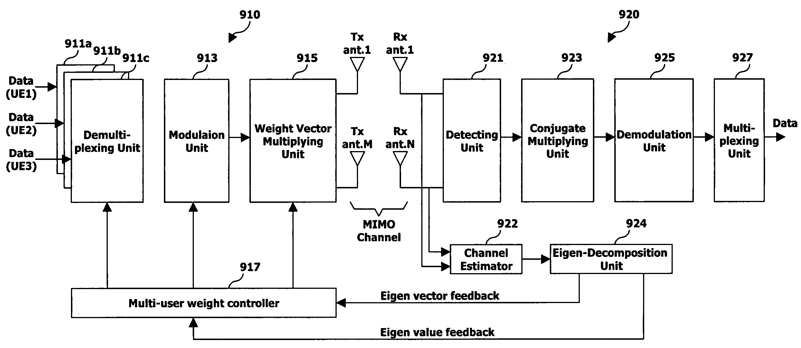
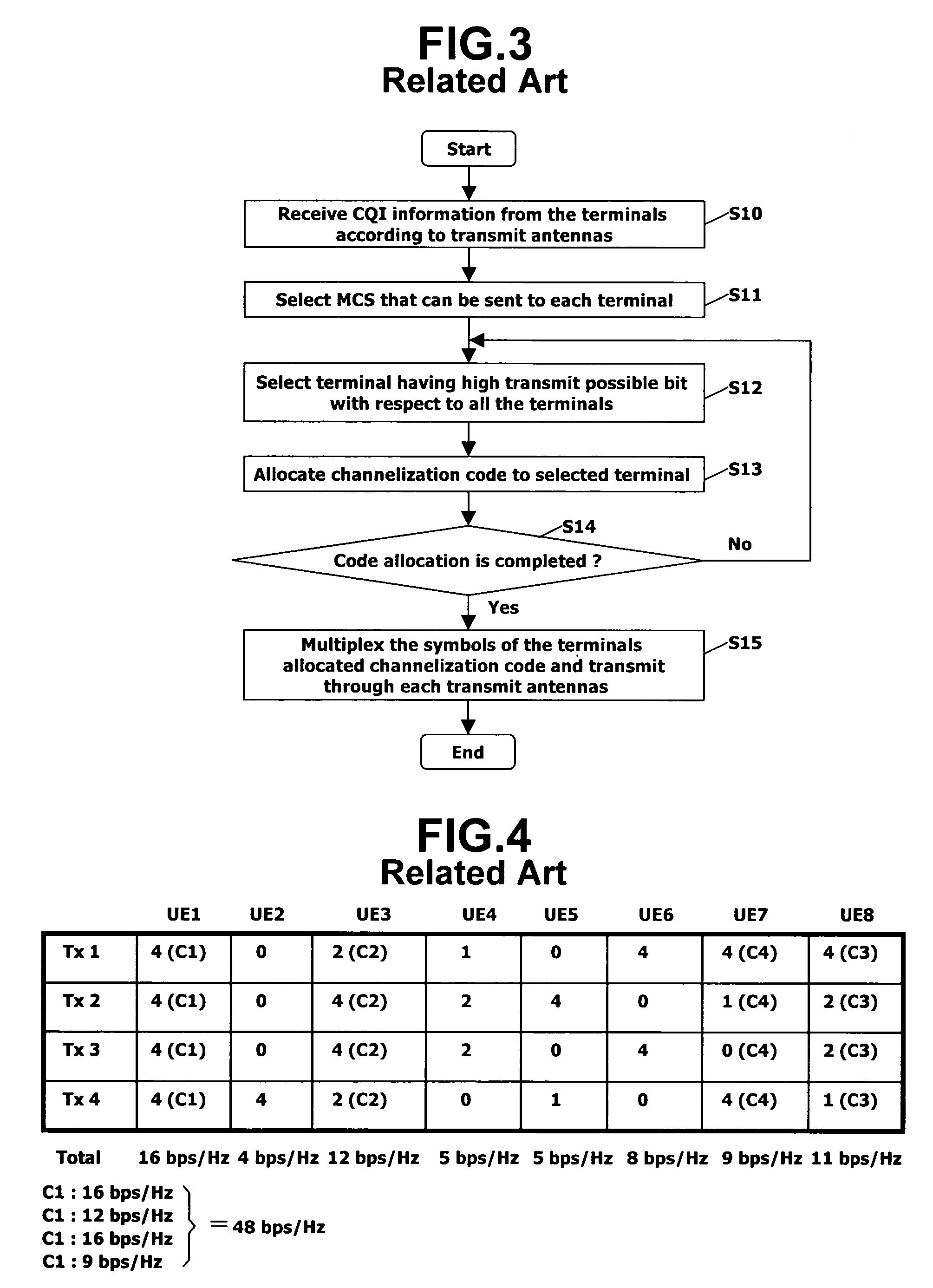
[0086]In general, the channel quality of each transmit antenna in a MIMO system employing multiple antennas at the transmit and receive ends. Namely, even if the overall channel quality of the transmit antennas with respect to a particular terminal (user) is satisfactory, the channel quality between each antenna and various terminals may not be satisfactory. Thus, even if the link quality between the base station and the terminal is considered to be good, in actuality, there may be some links that are considered very good, while other links that are considered not good.

[0087]Accordingly, unlike the related art that considers the maximum ‘transmit possible bit number’ with respect to all antennas when allocating channelization codes, the invention provides a scheme that determines the maximum ‘transmit possible bit number’ (i.e., the channel state or condition) for each antenna when allocating channelization codes.

[0088]Also, when multiple users simultaneously receive a service in a ...


PUM


Abstract

A data transmission method for a MIMO (Multiple-input Multiple-Output) system allowing multiple terminals to share channelization codes according to the channel states, by receiving channel information from terminals, allocating channelization codes for each transmit antenna based upon the received channel information, and transmitting data via each transmit antenna according to the allocated channelization codes. When there are many user terminals and if the number of channelization codes are limited, namely, when the total number of channel codes used to distinguish the terminals is less than the total number of terminals, channelization code sharing per transmit antenna among multiple terminals is performed, such that the throughput of data that can be sent by using each channelization code is increased.

Description

BACKGROUND OF THE INVENTION[0001]1. Field of the Invention[0002]The invention relates to communication systems, more particularly, to methods and apparatus for allocating channelization codes in a wireless communication system with multiple antennas.[0003]2. Description of the Background Art[0004]Due to the rapid development of wireless communications, there is an increasing need to provide various types of multimedia services (e.g., video, photos, animation, music, games, etc.) through wireless interfaces supporting higher capacity data transmissions and higher data transmission rates. Accordingly, methods for allowing more efficient use of limited bandwidth are becoming more critical. To address these issues, new data transmission techniques using multiple antennas are being developed, and the so-called “MIMO” (Multiple-input Multiple-Output) technique is one such example.[0005]FIGS. 1 and 2 show the structures of a transmit end and a receive end for a PARC (Per Antenna Rate Contr...

Claims


Application Information

Patent Timeline
Patent Type & Authority Patents(United States)
IPC IPC(8): H04B7/02H04B7/06H04J99/00
CPCH04B7/061H04B7/0626H04B7/0634H04B7/0417
Inventor SEO, DONG-YOUNKIM, BONG-HOESHIM, DONG-HEEKOO, HYOUNHEE
Owner LG ELECTRONICS INC
Why Eureka
Try Eureka