Message exchange and method for distributing messages in telephone networks

a telephone network and message exchange technology, applied in special services for subscribers, substation equipment, electrical appliances, etc., can solve the problems of not being able not being able to direct reply to the writer of the message, and not being able to make it possible for a user to transmit a message to a plurality of addressees

Inactive Publication Date: 2008-05-13
SWISSCOM
View PDF21 Cites 8 Cited by
  • Summary
  • Abstract
  • Description
  • Claims
  • Application Information

AI Technical Summary

Benefits of technology

[0009]It is an object of this invention to propose a new device and a new method for receiving, storing and transmitting spoken messages in telephone networks which, in particular, make it possible to receive messages from a plurality of subscribers of a public switched telephone network.
[0010]In particular, these objects are achieved by embodiments of a message exchange which is connected to the public switched telephone network, and comprises a receiving module which can receive spoken messages from a plurality of subscribers in the telephone network via the telephone network. The device also stores a received message, in each case, together with an automatically determined identification, for example, the call number of the subscriber who has placed the message. Also, this message exchange comprises a transmission module which can transmit stored messages to the respective subscribers by means of an automatic call. Such a message exchange has the advantage that the subscribers in the telephone network do not need any special, personal terminals to store messages and transmit them to one or more subscribers in the telephone network. Moreover, a message transmitted and stored to such a message exchange can be clearly assigned to the transmitting subscriber so that results about the outcome of the message transmission and / or replies of the receiving subscriber can be transmitted to the transmitting subscriber.
[0013]In a another embodiment, the message exchange comprises a speech recognition module so that subscribers can address messages to subscribers and / or groups of subscribers by designating the respective subscribers or groups of subscribers by means of spoken speech and transmitting them to the message exchange. The speech recognition module identifies, in the list of the respective subscribers, the subscribers and / or groups of subscribers designated by the subscriber. Moreover, in an embodiment variant, this speech recognition module makes it possible for subscribers to create and administer the lists by means of spoken language.

Problems solved by technology

Moreover, the telephone call device described in EP 0 377 379 A1 does not make it possible for a user to transmit a message to a plurality of addressees.
However, the radio telephone system described in EP 0 177 405 is designed for just one user, and does not allow the user to transmit a message to a plurality of addressees.
The method described in U.S. Pat. No. 5,146,487 is not designed to transmit a message to a plurality of addressees.
Although the method described is suitable for receiving and storing messages from a plurality of users, no direct reply can be transmitted to the writer of a message.

Method used


Image

  • Message exchange and method for distributing messages in telephone networks
  • Message exchange and method for distributing messages in telephone networks
  • Message exchange and method for distributing messages in telephone networks

Examples


second embodiment

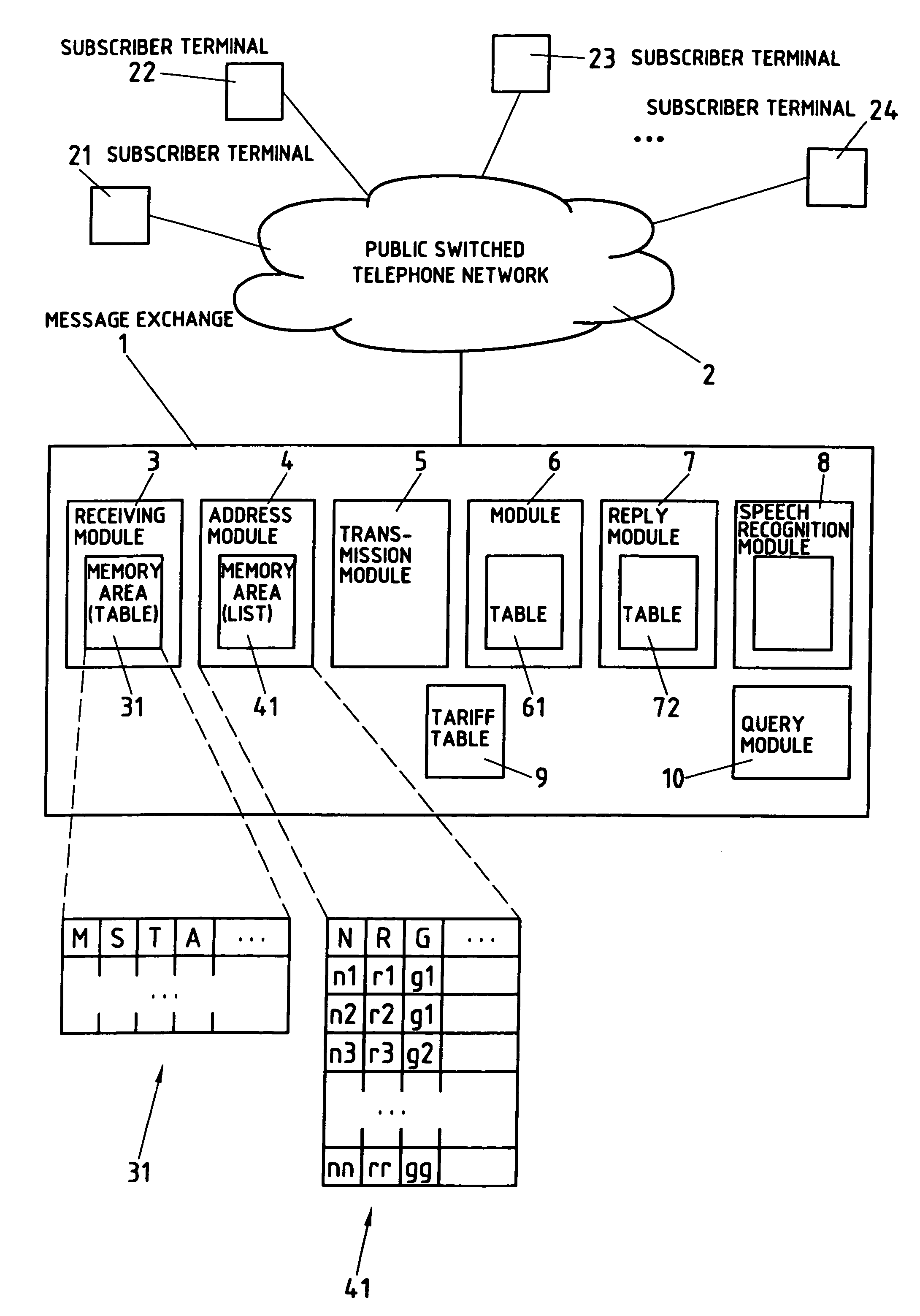
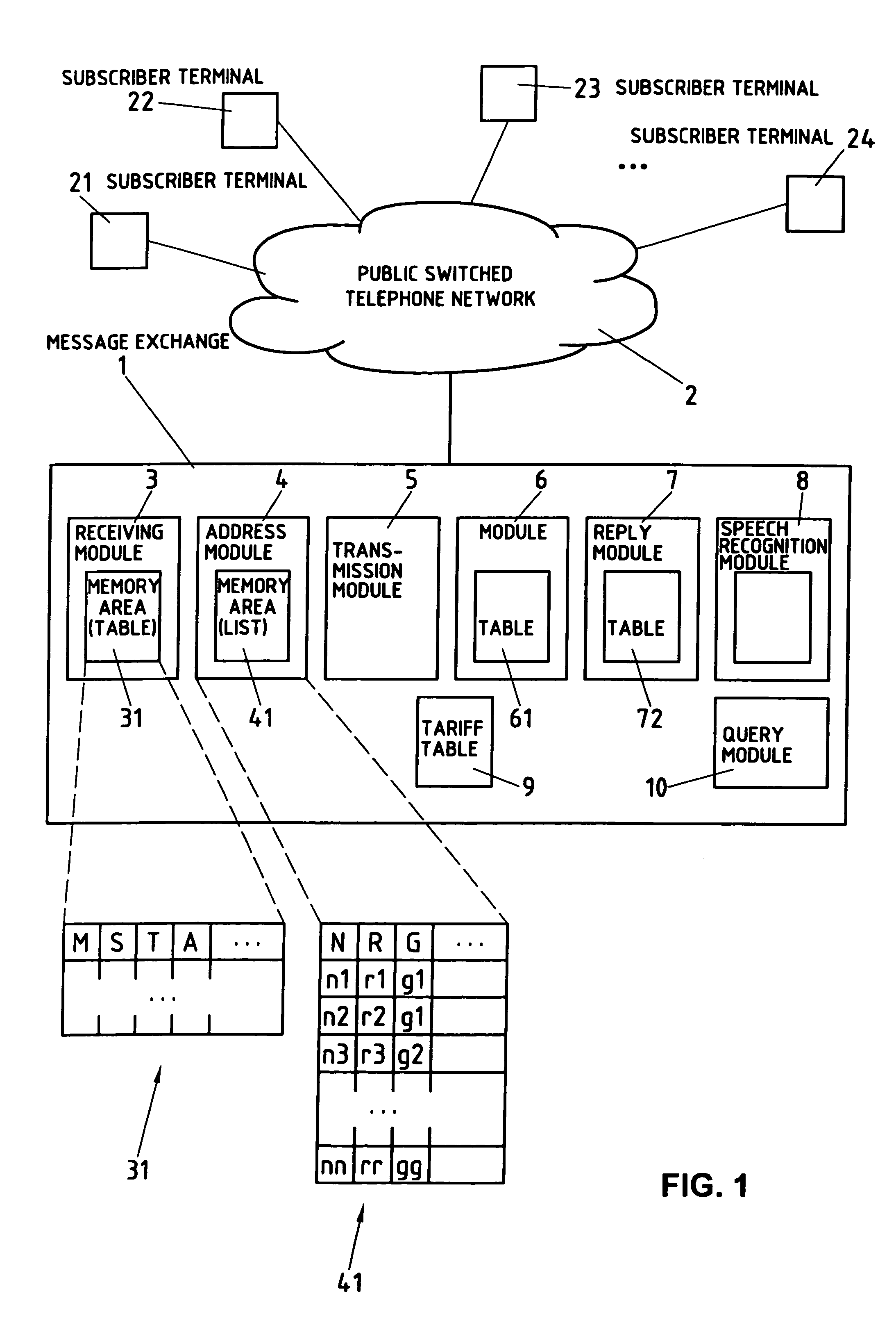
[0025]In a second embodiment above, the transmitting subscriber determines the addressee by entering the name by means of the selection keys of his terminal or an identification number of a subscriber or a group of subscribers by means of selection keys of his terminal. In this variant, the typed-in name or the identification number is received by the receiving module 3 and compared, for example, with the entries in a personal list 41 of the transmitting subscriber 21, the administration of which will be described later. As can be learned from the table 41, illustrated schematically in FIG. 1, the value of the entered group G=g1 corresponds, for example, to two subscribers with the names N=n1 and N=n2, or respectively their call numbers R=r1 and R=r2, or the value of the entered name N=n3 corresponds to the call number R=r3. The receiving module 3 can correspondingly enter the call numbers r1 and r2, or respectively r3 in table 31, as the identification of the subscribers to whom th...

third embodiment

[0026]In a third embodiment, the transmitting subscriber 21 determines the addressees by transmitting the names thereof and / or the name of a group of subscribers by means of spoken language to the message exchange 1, where they are received by the receiving module 3. In a similar way as in the second variant, the receiving module 3 compares the received names and / or names of groups with the entries in the above-mentioned personal list 41 of the transmitting subscriber 21, and determines the call numbers belonging thereto. In addition, the services of a speech recognition module 8 of the message exchange 1 can be used thereby, which are based on commercially available software programs and which convert the received spoken names into text that is compared with the alphanumerically stored names and / or group names of the personal list 41. As an alternative, the receiving module 3 can have at its disposal programmed comparison algorithms by means of which the received spoken names are c...


PUM


Abstract

A voice-controlled message exchange apparatus and method for receiving spoken messages, from a plurality of subscribers in a public switched telephone network via the telephone network. The voice controlled message exchange is used for storing the received messages, together with an identification of the subscriber, who has transmitted the message, transmitting these messages to one or more subscribers or groups of subscribers in the public switched telephone network, and accepting and storing replies from subscribers, to whom the messages were transmitted, whereby the subscribers not only give voice-controlled messages and replies, but can also draw up and administrate lists with identifications of subscribers and groups of subscribers by voice control.

Description

[0001]This application is the national phase of international application PCT / CH98 / 00407 filed Sep. 22, 1999 which designated the U.S. and that application was published under PCT Article 21(2) in EnglishBACKGROUND OF THE INVENTIONDiscussion of the Background[0002]1. Field of the Invention[0003]The present invention relates to a message exchange and a method for disseminating messages in telephone networks. In particular it relates to a message exchange and a method for receiving and storing spoken messages and for transmitting these messages to one or more subscribers, to whom the messages are addressed, in a public switched telephone network.[0004]2. Description of the Related Art[0005]Patent document EP 0 377 379 A1 describes an automatic telephone call device, which makes it possible to store messages and associated transmission profiles with the number of the addressee, date and point in time of the first message transmission, frequency of further transmission attempts as well ...

Claims


Application Information

Patent Timeline
Patent Type & Authority Patents(United States)
IPC IPC(8): H04M1/64H04M15/00H04M3/50H04M3/53H04M3/533H04M11/00H04M11/04H04Q3/00
CPCH04M3/53H04M3/5307H04M3/533H04M11/00H04M11/04H04Q3/0045H04Q3/0091
Inventor MESSMER, BRUNO T.
Owner SWISSCOM
Why Eureka
Try Eureka