Rotary bed comprising an improved rotary hinge

a technology of rotary bed and hinge, which is applied in the field of rotary bed, can solve the problems of preventing the base from being set, reducing the clearance between the reclining frame and the head end of the bed, and reducing the structural height of the rotary hinge, so as to eliminate the danger reduce the clearance between the reclining frame and the head end of the bed, and reduce the risk of pinching and cutting points

Inactive Publication Date: 2008-05-20
BARTHELT HANS PETER
View PDF13 Cites 35 Cited by
  • Summary
  • Abstract
  • Description
  • Claims
  • Application Information

AI Technical Summary

Benefits of technology

[0010]According to the invention, a rotary hinge can be provided that has a supporting ring, within which the swiveling bolster is located and to which the reclining frame is directly or indirectly attached. The swiveling bolster is connected exclusively via the supporting ring to the base, whereby no center axial peg is required. Therefore, the area within the swiveling bolster is free. This clearance enables the accommodation of parts of the drive devices for the back and the foot sections of the reclining frame, which is advantageous for reducing the structural height.
[0025]With the present invention, brackets are provided, which run in the longitudinal direction of the corresponding spar and which form the hinge brackets. Between every two brackets forming a hinge, at least one circular disk shaped spacing element is arranged. The spacing element is preferably greater in diameter than the vertical extent of the corresponding longitudinal spar. Thus in each pivoting position of the spars relative to each other, pinching and clamping positions are effectively prevented.

Problems solved by technology

This would thereby make standing up more difficult.
The structural height of the rotary hinge is relatively great, which requires that the base contact the floor directly without any free clearance.
These issues prevent the base from being set on feet in the known rotary bed; instead the bed must directly contact the floor with the lower spars or braces.
However, such an arrangement is unfavorable ergonomically since care personnel must maintain a spacing corresponding to the size of their feet from the reclining frame.
At best, the care personnel can place their feet directly on the base, which results in a considerable spacing between the lower leg of the care personnel and the edge of the reclining frame.
The care personnel cannot be supported with the lower leg or knee against the edge of the bed when caring for the patient in the bed, so that ergonomically unfavorable proportions are created.

Method used


Image

  • Rotary bed comprising an improved rotary hinge
  • Rotary bed comprising an improved rotary hinge
  • Rotary bed comprising an improved rotary hinge

Examples


Embodiment Construction

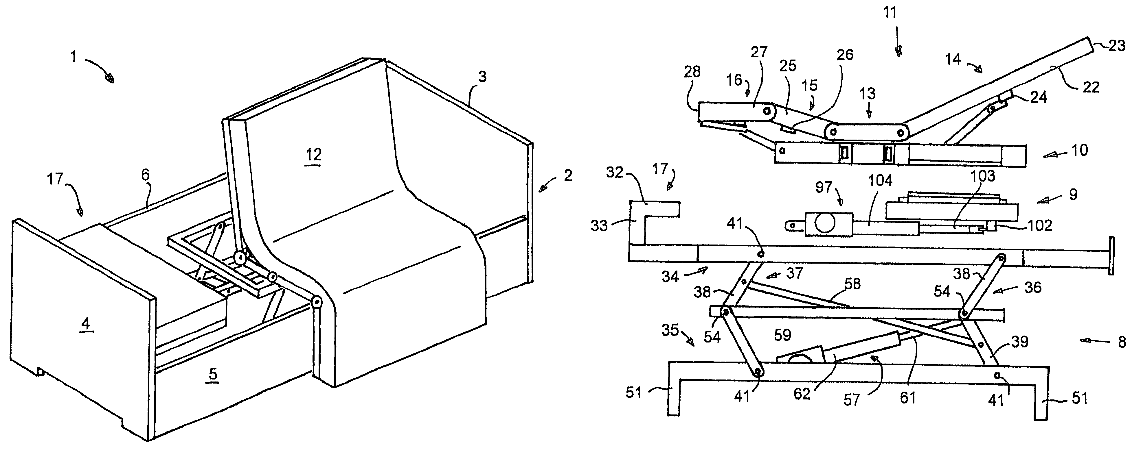
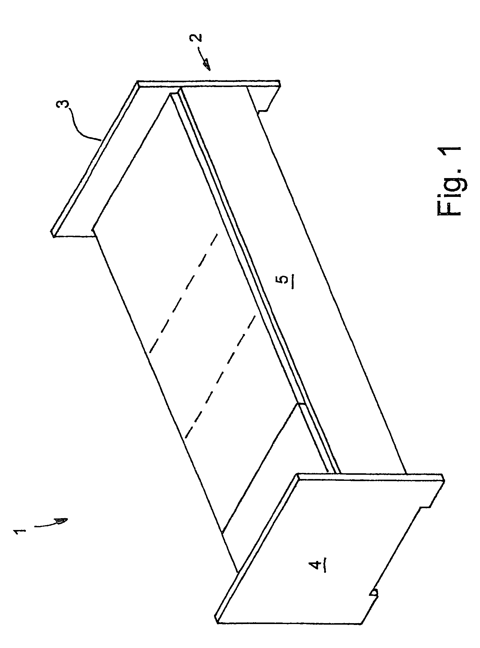
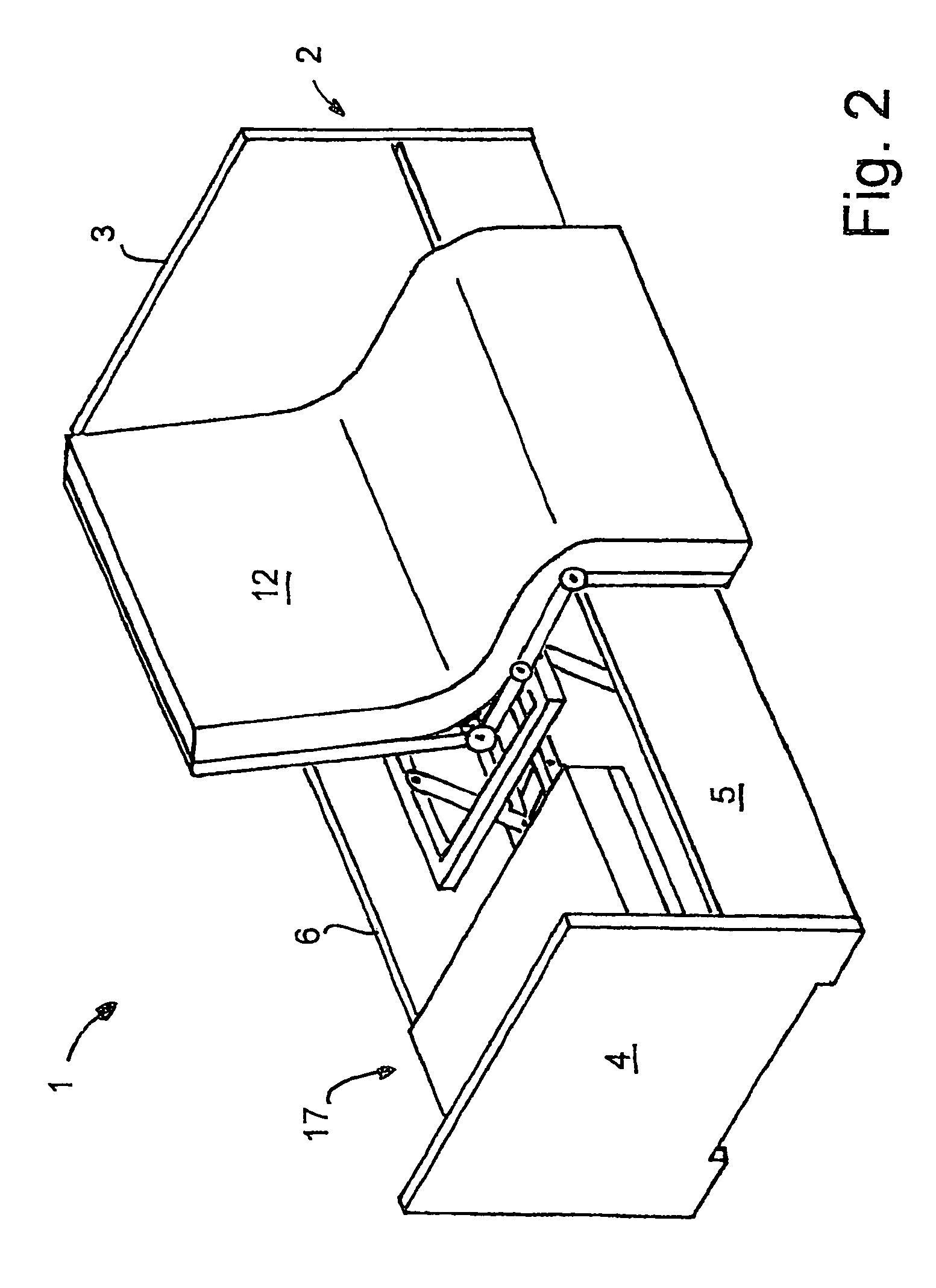
[0039]FIG. 1 provides a perspective view of a nursing bed 1 in the reclining position, while FIG. 2 illustrates the nursing bed 1 in the sitting or chair position. The nursing bed 1 has a bed border 2 with a head part 3, a foot part, as well as side walls 5 and 6. The proximal side wall 5 with reference to FIGS. 1 and 2 is located in the reclining position as shown at a distance to the floor, whereby there is a gap that enables care personnel to place their toes under the bed, between the lower edge of the side wall 5 and the floor. The side wall 5 is supported so that it can move, and, in the chair position of the nursing bed 1, reach a position shifted downward, as can be recognized from FIG. 2. The special bearing of the side wall 5 is explained in detail, e.g., in DE 199 12 937 A1 the disclosure of which is incorporated herein by reference.

[0040]Within the bed border 2, there is a bed framework 7, as shown in FIGS. 3 and 4. The bed framework 7 includes a height adjustable base 8...


PUM


Abstract

A nursing bed is provided that has a height adjustable base, in which a rotary hinge is attached in a substantially countersunk arrangement. The rotary hinge connects the base to an intermediate frame on which the actual reclining frame is installed. In this way, a bed framework is obtained, which, after subtracting the height of support feet, has a very small structural height, so that in the lowest position, the distance from top edge of the mattress from the floor corresponds to the length of a lower leg, while simultaneously there is still space underneath the base.

Description

FIELD OF INVENTION[0001]The present invention generally relates to a rotary bed such as used in nursing applications.BACKGROUND OF THE INVENTION[0002]From practice, a rotary bed is known, in which a reclining frame is arranged on a height adjustable base. The reclining frame is connected to the base by means of a rotary hinge. The reclining frame is essentially separated into three sections: a back section, a central section, and a leg section. The leg section is divided into a proximal and a distal lower section.[0003]With the aid of electromotive drive devices, the reclining frame can be converted from a more or less elongated reclining or bed position into a seat position. For this purpose, the reclining frame is brought 90° from the reclining position into a position perpendicular to the base with the aid of the rotary hinge. The back section of the reclining frame is raised while the distal lower section of the leg section is lowered downward. The central section and also the p...

Claims


Application Information

Patent Timeline
Patent Type & Authority Patents(United States)
IPC IPC(8): A61G7/015A61G7/00A61G7/053A61G7/10
CPCA61G7/015A61G7/05A61G7/012A61G7/053A61G7/16
Inventor BARTHELT, HANS-PETER
Owner BARTHELT HANS PETER
Why Eureka
Try Eureka