Airfoil blade of a bearingless rotor of a helicopter

Active Publication Date: 2013-10-24
AIRBUS HELICOPTERS DEUT GMBH
View PDF13 Cites 11 Cited by
  • Summary
  • Abstract
  • Description
  • Claims
  • Application Information

AI Technical Summary

Benefits of technology

[0022]Particularly according to the invention, the distances of each of the two openings from the pitch axis of the airfoil blade can be different, to optimize the folding of the airfoil blade and to improve the lead lag kinematics by increasing the distances. Particularly according to the invention, the airfoil blade includes a main opening and a supporting opening that are both arranged lying perpendicular to the lead-lag pivoting plane of the rotor blade. In this context, the lead-lag pivoting plane essentially corresponds to the rotation plane of the rotor blade. The inventive airfoil blade achieves the advantage that the lead-lag pivoting stiffness at the separable or releasable junction is substantially increased by the maximized distance between said one main opening and said supporting opening. Said main opening and said supporting opening configuration allow an integration at a suitable location of the inventive airfoil blade more easily than the arrangement of a plurality of equally charged openings provided with any of the prior art arrangements. Said main opening is located nearby the maximum thickness of the profile of the blade attachment. The invention allows a reduced total structural height at an extended width of the profile of the airfoil blade without detracting from the mechanical strength of the junction.
[0023]Consequently the inventive airfoil blade achieves to configure the control cuff with a reduced profile height at the root end of said airfoil blade and therewith provide an improved overall aerodynamic configuratio

Problems solved by technology

During operation, the rotor blades are deflected in various directions and are thereby subjected to high loads in these various directions.
The separable or releasable junction is subject to high technical and mechanical

Method used


Image

  • Airfoil blade of a bearingless rotor of a helicopter
  • Airfoil blade of a bearingless rotor of a helicopter
  • Airfoil blade of a bearingless rotor of a helicopter

Examples


Example

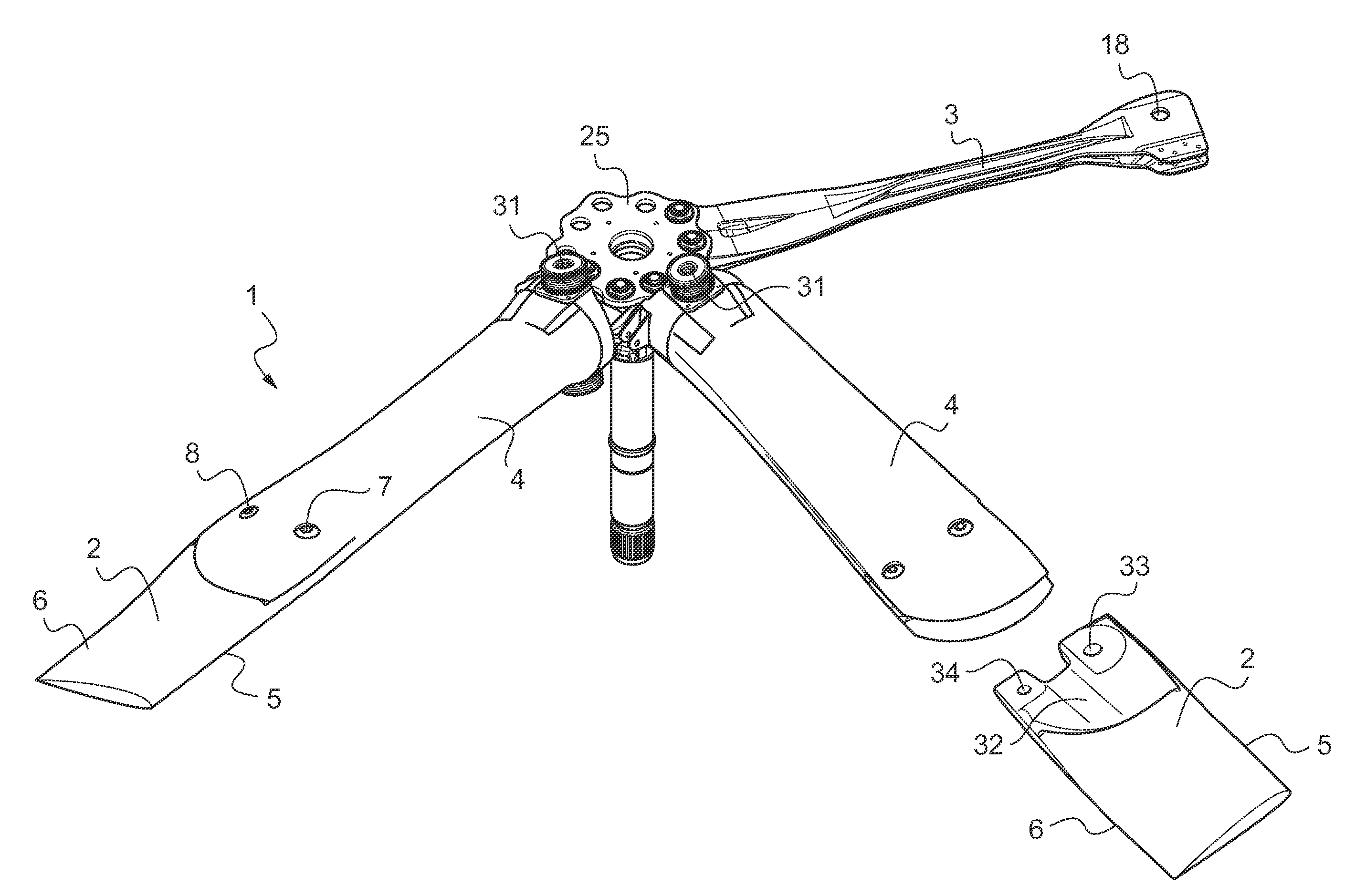
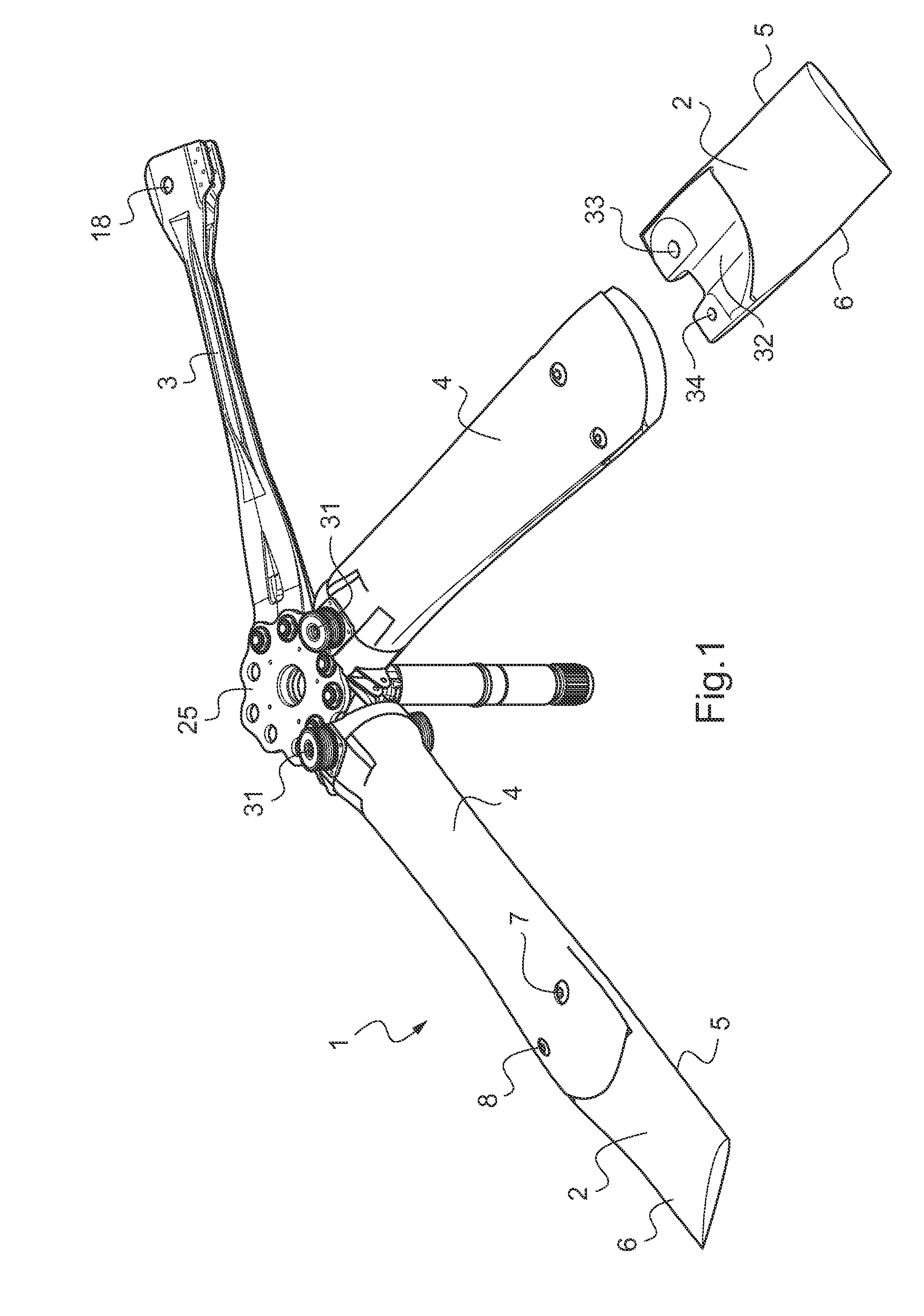
[0035]According to FIG. 1 a blade attachment 1 for a bearingless rotor of a helicopter (not shown) comprises an airfoil blade 2, a flexbeam 3 and a torsion stiff control cuff or torque tube 4 enclosing the flexbeam 3. The airfoil blade 2 is mounted by means of the flexbeam 3 and the control cuff 4 to a rotor head 25. Lead lag dampers 31 are arranged on the control cuffs 4 next to the rotor head 25.

[0036]The flexbeam 3 consists of a fiber-reinforced composite material. The root end of the flexbeam 3 is secured to the rotor head 25 of the helicopter (not shown). In operation each of the airfoil blades 2 rotate about an essentially vertical rotor head axis, whereby the airfoil blades 2 rotate with their lengthwise central axis in a rotor blade plane. This rotor blade plane substantially corresponds to the lead-lag pivoting or oscillating plane of the airfoil blades 2 of the bearingless rotor of the helicopter.

[0037]Each airfoil blade 2 has a leading edge 5 and a rear edge 6, a tip end ...


PUM


Abstract

An airfoil blade (2) of a bearingless rotor of a helicopter. Said airfoil blade (2) has a pitch axis from a tip end to a root end and said root end is provided with junction means for a separable junction arrangement of said airfoil blade (2) with a flexbeam head (13), and a control cuff (4, 22). Said junction arrangement is mechanical with removable fasteners respectively removable connecting said root end of said airfoil blade (2) to said control cuff (4, 22) and said flexbeam head (13). Said root end comprises at least two openings (7, 8) being asymmetric with regard to said pitch axis.

Description

CROSS-REFERENCE TO RELATED APPLICATIONS[0001]This application claims priority to European patent application No. 12 400012.6 filed Apr. 18, 2012, the disclosure of which is incorporated in its entirety by reference herein.BACKGROUND OF THE INVENTION[0002](1) Field of the Invention[0003]The invention relates to an airfoil blade of a bearingless rotor of a helicopter with the features of claim 1.[0004](2) Description of Related Art[0005]During operation, the rotor blades are deflected in various directions and are thereby subjected to high loads in these various directions. The rotor blades must be designed to withstand these high loads while still providing the required flexibility or articulation to allow the blades to carry out flapping, lead-lag oscillating, and pitch angle variation movements.[0006]Typically, a rotor blade of a bearingless rotor includes a structural element known as a flexbeam at the inner end of the blade connected to the rotor head. The flexbeam supports and t...

Claims


Application Information

Patent Timeline
IPC IPC(8): F01D5/30
CPCF01D5/30B64C27/33B64C27/50B64C11/04B64C27/00B64C27/04B64C27/54
Inventor KUNTZE-FECHNER, GERALDBAUER, MARKUSORTNER, MARTIN
Owner AIRBUS HELICOPTERS DEUT GMBH
Why Eureka
Try Eureka