Switch and method for manufacturing the same

a technology of switching speed and manufacturing method, applied in the field of switches, can solve the problems of reducing operation speed, complicated fabrication process, and difficulty in increasing switching speed, and achieve the effects of reducing structure height, high speed, and ensuring signal transmission efficiency

Inactive Publication Date: 2006-01-31
PANASONIC CORP
View PDF7 Cites 11 Cited by
  • Summary
  • Abstract
  • Description
  • Claims
  • Application Information

AI Technical Summary

Benefits of technology

[0012]It is an object of the present invention to provide, in order to solve the problem, a switch having a movable electrode to be separately driven upwardly and downwardly thereby securing a signal transfer efficiency and insulation capability, and performing signal connection and disconnection at a high speed without the need for a structure height.
[0013]In order to solve the above object, a switch of the present invention comprises a movable electrode, a signal-transmitting fixed electrode positioned beneath the movable electrode, and a movable electrode driving fixed electrode positioned on both sides of the movable electrode with respect to lengthwise direction thereof. Convex and concave parts are formed in a side surface of the movable electrode. The movable electrode driving fixed electrode is formed with concave and convex parts corresponding to the convex and concave parts in the side surface of the movable electrode. The convex parts formed in the side surface of the movable electrode are arranged to be surrounded by the concave parts formed in the movable electrode driving fixed electrode, while the convex parts of the movable electrode driving fixed electrode are arranged to be surrounded by the concave parts in the side surface of the movable electrode. The downward driving of the movable electrode is made by an electrostatic force acted between the signal transmitting fixed electrode positioned beneath the movable electrode and the movable electrode, while the upward driving of the movable electrode is by an electrostatic force acted between the convex and concave parts of the movable electrode driving fixed electrode and the concave and convex parts formed in the side surface of the movable electrode. Accordingly, separation is possible between downward driving and upward driving, making it possible to reduce the structure height, secure signal transmission efficiency and insulation, and connect and disconnect a signal at a high speed.
[0014]Furthermore, the movable electrode, convex and concave parts in the side surface of the movable electrode, concave and convex parts of the movable electrode driving fixed electrode and a part of the movable electrode driving fixed electrode are formed on a resist sacrificial layer, the process for removing the sacrificial layer can be conducted by a dry process. This makes it possible to prevent an adsorption to an unintended region due to surface tension, i.e. so-called sticking, which is problematically encountered in a liquid process after removing the sacrificial layer.

Problems solved by technology

However, in the case to disconnect a signal being conveyed to the ground line 2503, there is difficulty in increasing the switching speed, because the operation is carried out only by the spring returning force of a material structuring the ground line.
However, this involves problems, e.g. decreasing operation speed in switching from the transmission line 2502 to the ground line 2503, and requiring to increase the voltage to be applied to between the ground line 2503 and the transmission line 2502.
This makes the fabrication process complicated.
It is practically impossible to carry out a process of forming a pattern or the like over such a high step.
This, however, further increases the response time.
As a result, there is needed to form an electrode at the part not directly involved in signal connection and disconnection, increasing the overall mass of the movable electrode.
This is disadvantageous in connection and disconnection at a high speed.
However, those for driving in a vertical direction to a substrate require to form a structure in a height direction, making the fabrication process complicated.

Method used


Image

  • Switch and method for manufacturing the same
  • Switch and method for manufacturing the same
  • Switch and method for manufacturing the same

Examples


first exemplary embodiment

1. First Exemplary Embodiment

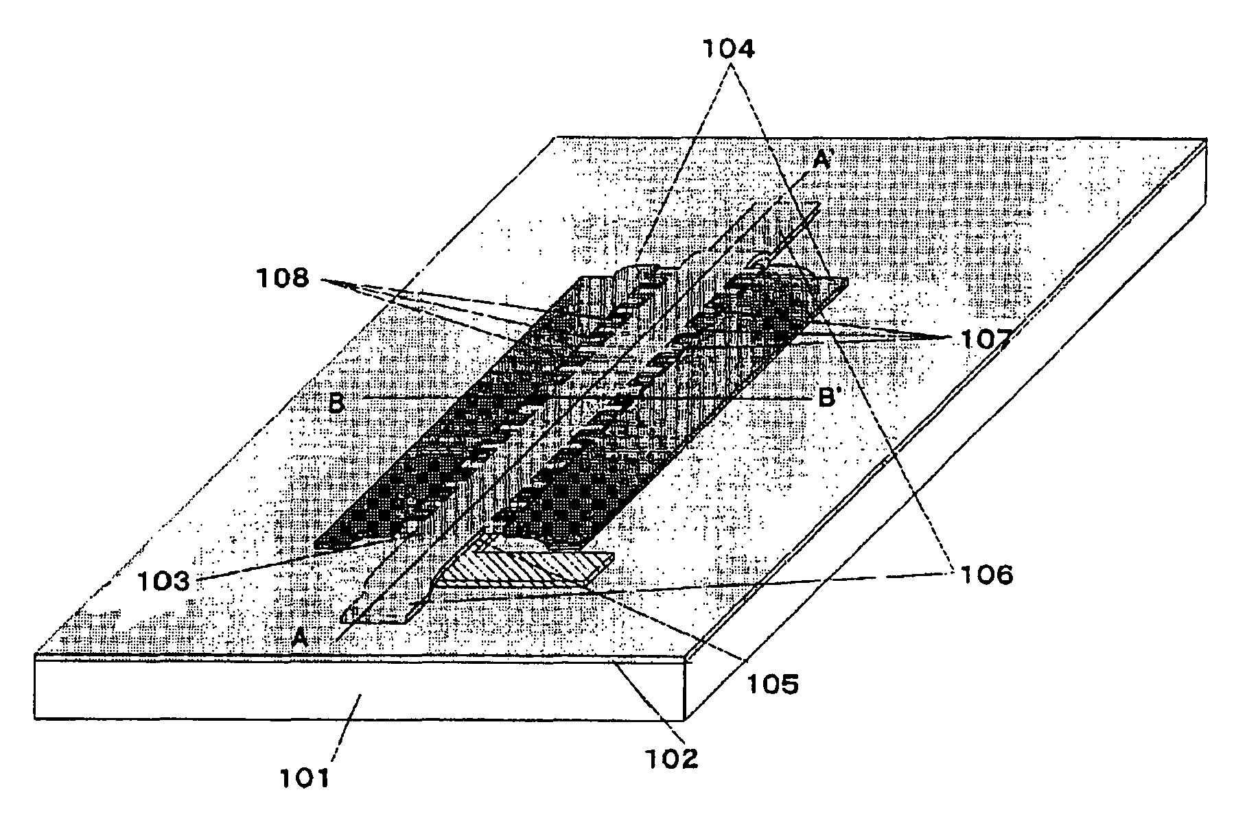
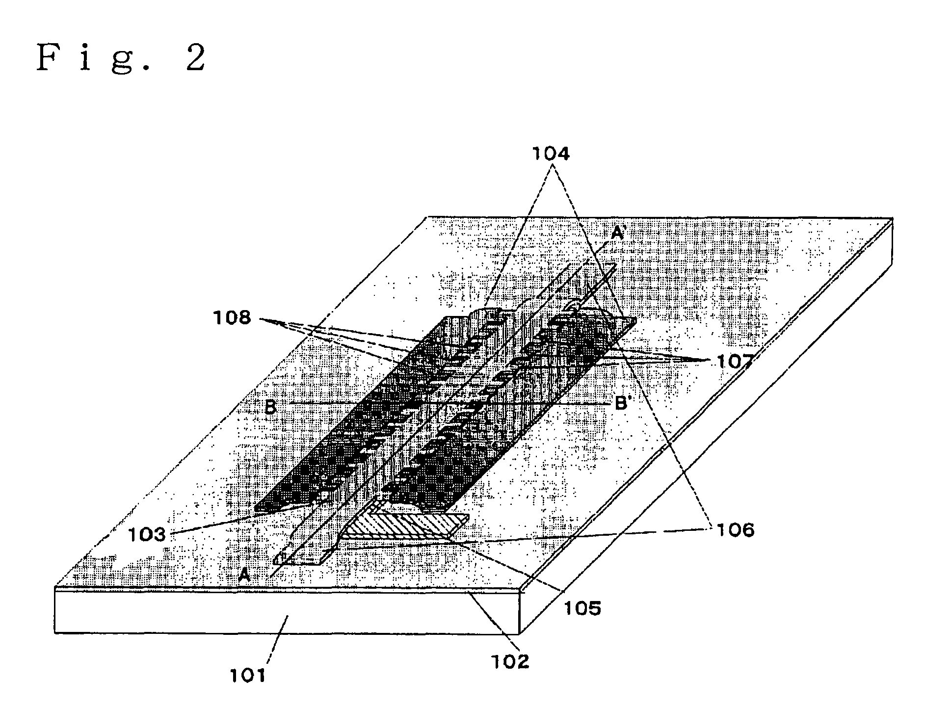
[0043]FIG. 2 is a perspective view of a switch in embodiment 1 of the present invention. This is structured by a movable electrode 103, a movable electrode driving fixed electrodes 104 and a signal transmitting fixed electrode 105, that are formed on a high resistive silicon substrate 101 through a silicon oxide film 102. The movable electrode 103 has a plurality of convex parts 107 in side surfaces thereof. In this embodiment 1, the convex parts 107 are assumed to be made all in the same form for convenience sake, and arranged at a periodic interval. Concave parts are formed between one convex part 107 and the adjacent convex part 107. The concave parts are also arranged at a periodic interval. The movable electrode driving fixed electrode 104 also has a plurality of convex parts 108 arranged, in its side surface, correspondingly to and surrounded by the concave parts of between the convex parts 107 on the side surface of the movable electrode. The conc...

second exemplary embodiment

2. Second Exemplary Embodiment

[0056]The force acted upon the electrodes having a combination of convex and concave parts is described, e.g. in IEEE MEMS 2002 Tech. Dig., p532, 2002. In the case of displacement-z, the force acted in a z-direction is given by Equation 4.

Fz=∂(CV2 / 2) / ∂z  Equation 4

[0057]In equation 4, V is the application voltage to the electrode, C is the capacitance formed between the electrodes, and z is given as a displacement. From Equation 4, it can be seen that, even where there is no capacitance change formed between the electrodes when there is a displacement change in the z-direction, an electrostatic force does not takes place. Accordingly, in the case that, for example, the movable electrode driving fixed electrode 104 is greater than the movable electrode 103 in thickness as shown in FIG. 9, the capacitance region 901 in the movable electrode driving fixed electrode 104 and movable electrode 103 is not changed in area by a somewhat movement of the movable e...

third exemplary embodiment

3. Third Exemplary Embodiment

[0060]As shown in FIG. 10A, the convex part 1004 on the side surface of the movable electrode 1002 and the concave part 1005 of the movable electrode driving fixed electrode 1001 have a predetermined gap 1003 having an even distance d between them. However, in the case the movable electrode 1002 and the movable electrode driving fixed electrode 1001 are formed through the use of different masks, when a misfit occurs between the mask for forming a movable electrode and the mask for forming a movable electrode driving fixed electrode, the result is as shown in FIG. 10B. Namely, the gap on one side between the convex part 1004 on the side surface of the movable electrode and the concave part 1005 of the movable electrode driving fixed electrode 1001 is narrowed into d−e, i.e. a narrow gap 1013. The gap between the concave part 1005 and the concave part 1005 on opposite side is broadened into d+e, i.e. a wide gap 1014. Namely, FIG. 10B shows a relationship b...


PUM


Abstract

Disclosed is a switch having a movable electrode to be separately driven downward and upward to secure signal transmission efficiency and insulation capability and operate for signal connection and disconnect at a high speed. The switch comprises a movable electrode, a fixed electrode positioned beneath the movable electrode, and a movable electrode driving fixed electrode positioned on both sides of the movable electrode with respect to a length wise direction thereof. Inside surfaces of the movable electrode, concave and convex parts are formed to arrange on both sides fixed electrodes having the corresponding concave and convex parts with a space.

Description

FIELD OF THE INVENTION[0001]This invention relates to a switch improved in operation speed upon turning on / off and to a method for manufacturing such a switch.BACKGROUND OF THE INVENTION[0002]There is known a conventional signal switch as described in IEEE IEDM Tech. Digest 01, p921, 2001, for example. This is structured with a signal transmission line 2502 formed on a high-resistance silicon substrate 2501, a movable ground line 2503 arranged over the signal transmission line 2502 through a predetermined gap, and a ground line 2504, as shown in FIG. 1A. In this switch, a voltage is applied across a parallel plate capacitance comprising the movable ground line 2503 and signal transmission line 2502, whereby an electrostatic force is caused to put the movable ground line 2503 into contact with the signal transmission line 2502 through a high dielectric film 2505 as shown in FIG. 1B. By the contact, increased is the capacitance formed between the signal transmission line 2502 and mova...

Claims


Application Information

Patent Timeline
Patent Type & Authority Patents(United States)
IPC IPC(8): H01H51/22H01L27/04H01H1/06H01H11/00H01H11/04H01H59/00H01L21/822
CPCH01H59/0009
Inventor SHIMIZU, NORISATONAKANISHI, YOSHITONAKAMURA, KUNIHIKONAITO, YASUYUKI
Owner PANASONIC CORP
Why Eureka
Try Eureka