Electrical junction assemblies for coupling electrical fixtures to suspended ceiling grids

a technology of electrical junction assemblies and ceiling grids, which is applied in the direction of electric apparatus casings/cabinets/drawers, filing appliances, machine supports, etc., and can solve problems such as false employment, drop or suspend ceilings

Active Publication Date: 2008-05-20
FINELITE
View PDF27 Cites 36 Cited by
  • Summary
  • Abstract
  • Description
  • Claims
  • Application Information

AI Technical Summary

Problems solved by technology

Modem offices and schools often employ false, drop or suspended ceilings.

Method used


Image

  • Electrical junction assemblies for coupling electrical fixtures to suspended ceiling grids
  • Electrical junction assemblies for coupling electrical fixtures to suspended ceiling grids
  • Electrical junction assemblies for coupling electrical fixtures to suspended ceiling grids

Examples


Embodiment Construction

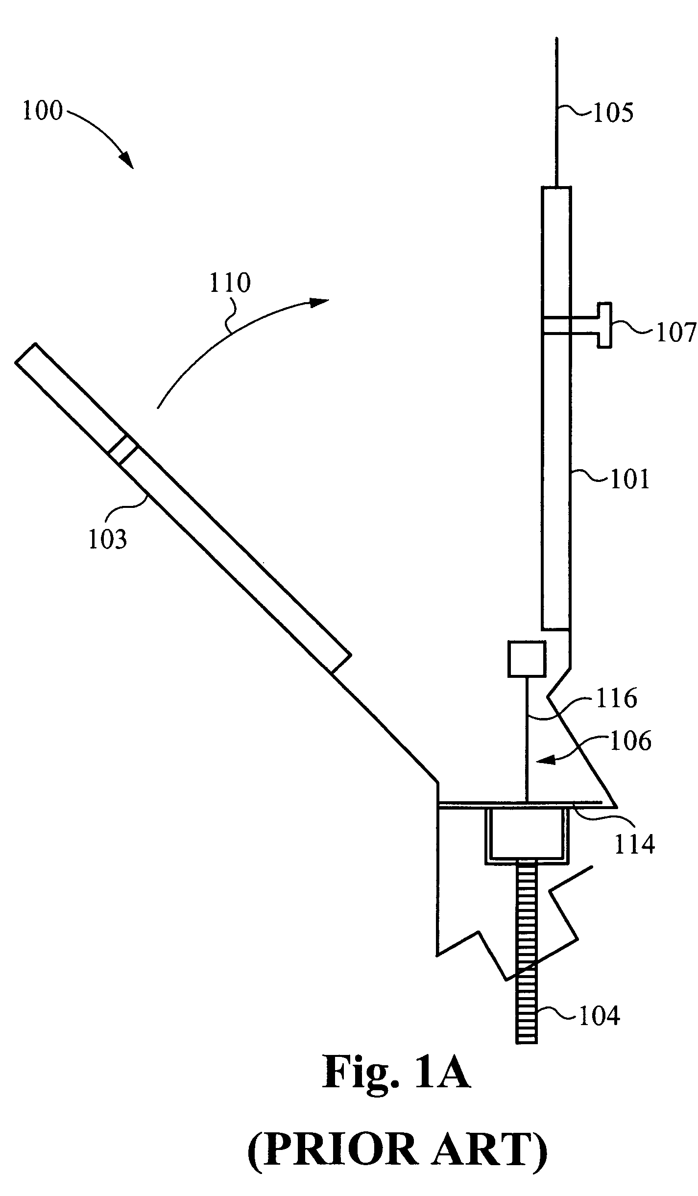
[0017]FIG. 1A shows side cross-sectional view of a prior art T-bar clip assembly 100 for mounting and suspending an electrical fixture (not shown) from a T-bar strcuture 106 that is used to form a T-bar grid that supports suspended ceiling tiles (not shown). The T-bar strcuture 106 has a vertical support 16 and horizontal flanges 114 for supporting removable ceiling tiles (not shown). The T-bar clip assembly 100 includes a first mounting bracket 101 and second mounting bracket 103 a that are clamped together and around the T-bar strcuture 106. A bolt feature 104 is attached to at least one of the first mounting bracket 101 and the second mounting bracket 103 therefrom.

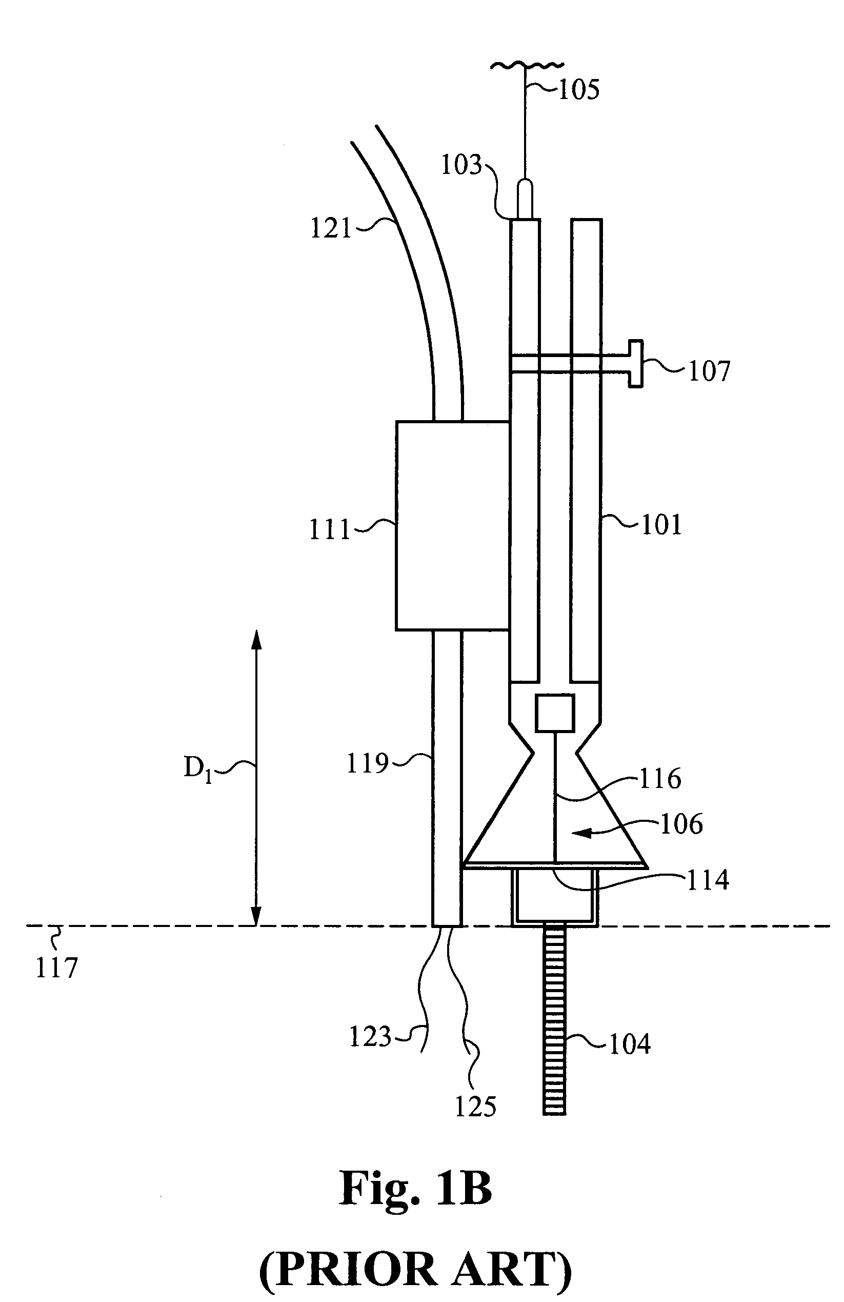
[0018]In order to install the T-bar clip assembly 100, the first mounting bracket 101 is fitted up to the T-bar structure 106. The second mounting bracket 103 is moved in a direction indicated by the arrow 110 to clamp around the T-bar structure 106, such as shown in FIG. 1B, and are secured together through a suitable...


PUM


Abstract

A T-bar clip assembly that securely couples to T-bar structures that are used to construct suspended ceiling is disclosed. The T-bar assembly is configured to support one or more electrical fixtures and provide power feeds to the one or more electrical fixtures. The T-bar clip assembly comprises support brackets that secure to the T-bar structures and one or more housing structures that attach to a portion of the support brackets to form one or more corresponding junction box enclosures. The junction box enclosures provide the power feeds to the one or more electrical fixtures at locations that are substantially flush with support flanges of the T-bar structure, an outer surface of the removable ceiling tiles or both.

Description

RELATED APPLICATION(S)[0001]This application claims priority under 35 U.S.C. § 119(e) from the U.S. provisional patent application Ser. No. 60 / 552,464, filed on Mar. 11, 2004, and titled “INTEGRATED TEE BAR CLIP AND ELECTRICAL SPLICE COMPARTMENT.” The provisional patent application Ser. No. 60 / 552,464, filed on Mar. 11, 2004, and titled “INTEGRATED TEE BAR CLIP AND ELECTRICAL SPLICE COMPARTMENT” is hereby incorporated by reference.FIELD OF THE INVENTION[0002]The invention relates to systems, devices for and methods of mounting and electrically coupling electrical fixtures to ceiling structures. More particularly, the present invention relates to systems, management systems, and devices for and methods of mounting and electrically coupling fixtures to suspended ceiling grids.BACKGROUND OF THE INVENTION[0003]Modem offices and schools often employ false, drop or suspended ceilings. A Suspended ceiling includes a grid of T-bar structures that support removable ceiling tiles. The T-bar s...

Claims


Application Information

Patent Timeline
Patent Type & Authority Patents(United States)
IPC IPC(8): H02G3/08A44B99/00B42F13/00H02G3/20H02G3/34
CPCH02G3/20H02G3/263H02G3/34Y10S248/906Y10T24/44923
Inventor HENDRICKSON, BRIAN S.CLARK, WALTER BLUE
Owner FINELITE
Why Eureka
Try Eureka