Rain tight fitting

a technology for tight fittings and conduits, applied in the direction of pipe joints, fluid pressure sealed joints, sleeves/socket joints, etc., can solve the problems of out-of-screwness and tolerances of electrical conduits, compression fittings using split rings rarely form rain tight fittings, and other flaws are typically found in electrical conduits, such as out-of-roundness and tolerances. out of specification

Active Publication Date: 2008-05-20
ARLINGTON INDS
View PDF25 Cites 22 Cited by
  • Summary
  • Abstract
  • Description
  • Claims
  • Application Information

AI Technical Summary

Problems solved by technology

Unfortunately, compression fittings of the type including a split ring very rarely form a rain tight fit on rigid conduit.
If a weld seam exists on the outer surface, a compression fitting using a split ring will not obtain a rain tight fit.
Other flaws are typically found in electrical conduit, including out-of-roundness and tolerances that are out of specification.
As a result of the typical non uniformities encountered in commercially available electrical conduit, compression fittings employing split rings seldom obtain a rain tight fitting as claimed by the fitting manufacturer.

Method used


Image

  • Rain tight fitting
  • Rain tight fitting
  • Rain tight fitting

Examples


Embodiment Construction

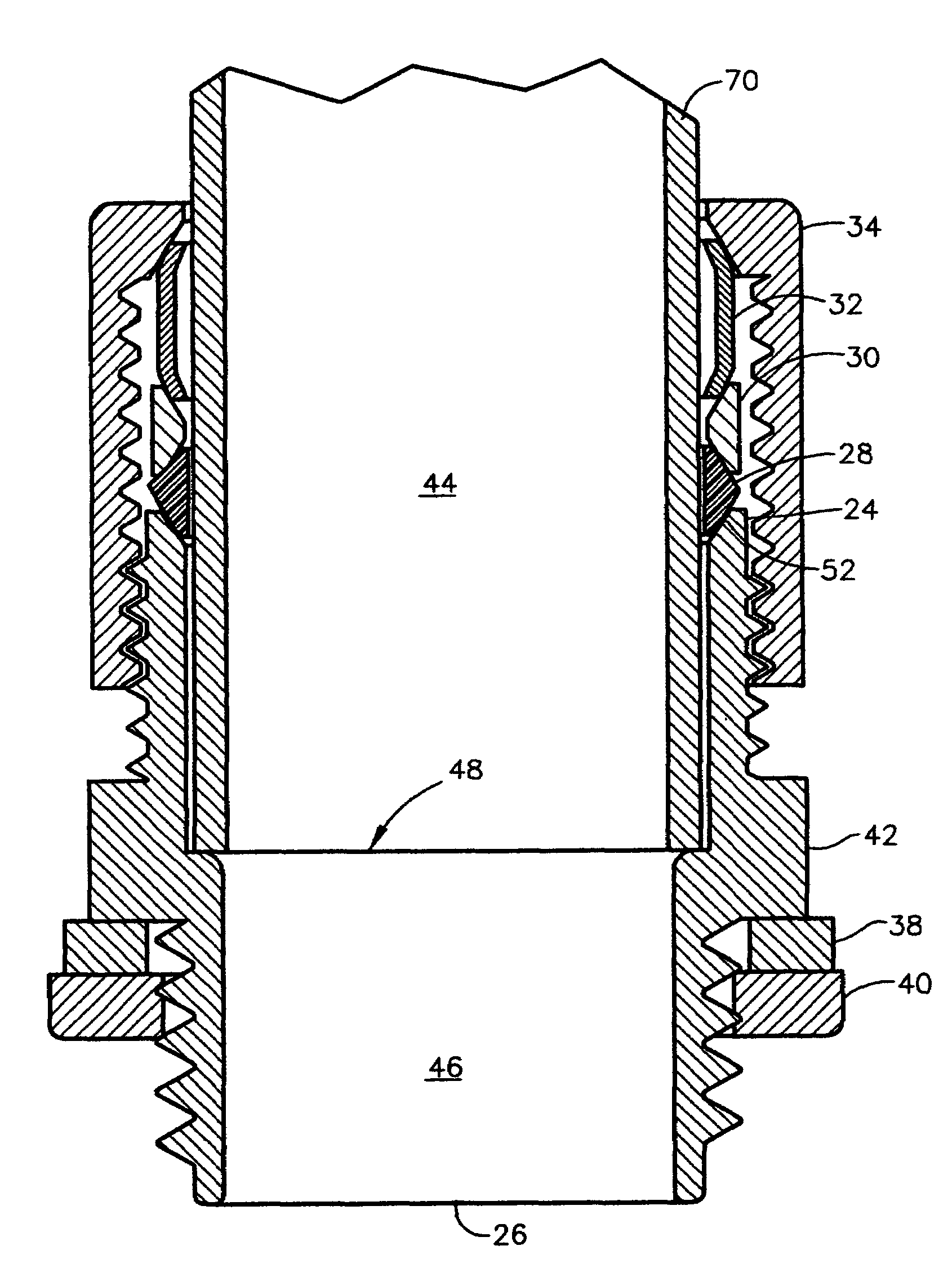
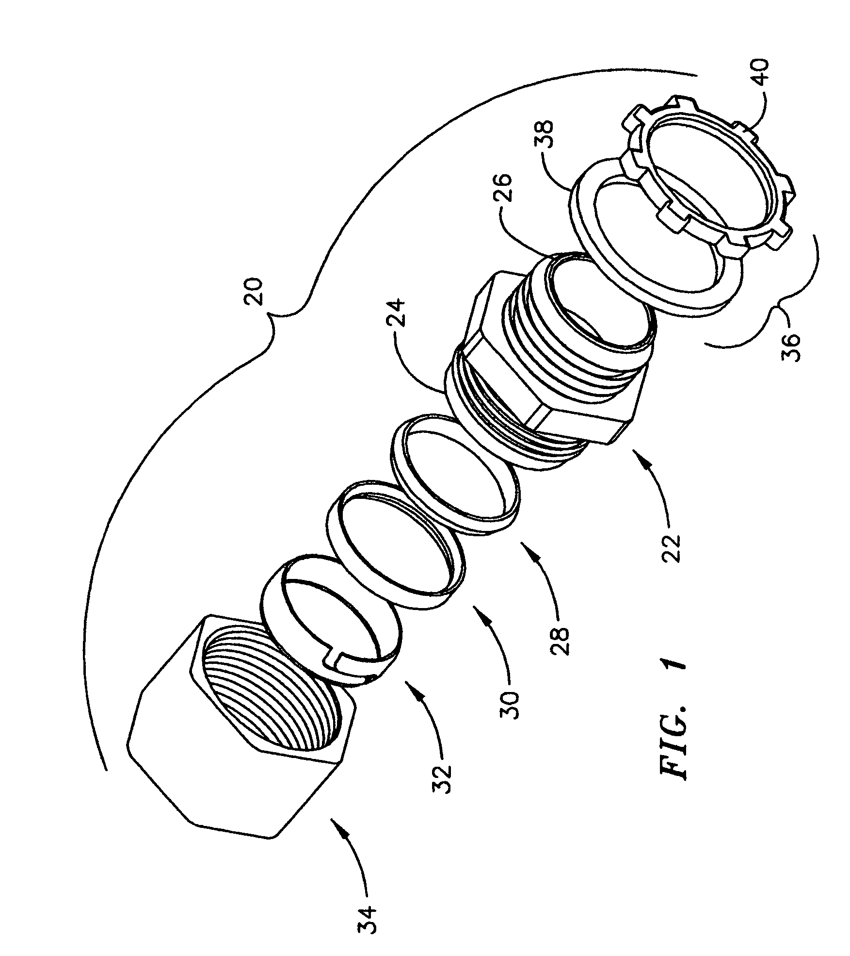
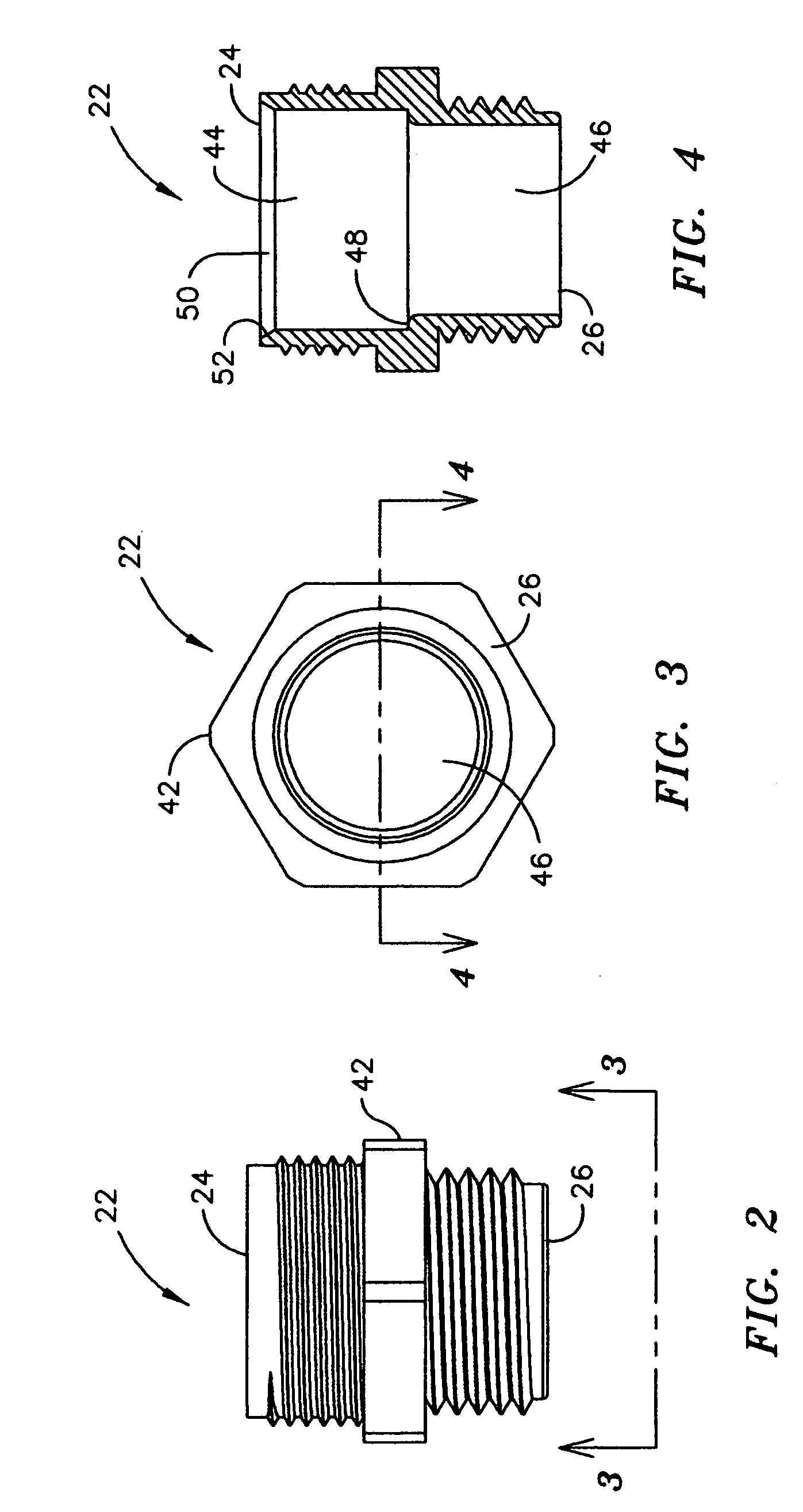
[0018]Referring to FIG. 1, an exploded view is depicted of a preferred embodiment of a rain tight fitting 20 according to the present invention. The rain tight fitting 20 includes a tubular body member 22 having a threaded rearward end 24 and a forward end 26, a first seal ring 28, a second seal ring 30, a compression ring 32, a compression nut 34 and a fastening arrangement 36 on the forward end 26. The ends of the fitting 20 are named in reference to the way they will interact with a panel (not shown) that they will be connected to. The forward end 26 of the fitting 20 will face the panel and the rearward end 24 will face away from the panel. The fastening arrangement 36 may consist of a forward seal ring 38 and a lock nut 40 as shown in FIG. 1, or, as shown in FIG. 10, may alternatively consist of a spring steel adaptor 41B and a washer 41A as disclosed in U.S. application Ser. No. 10 / 017,537, filed Oct. 22, 2001 to Gretz and incorporated herein by reference in its entirety.

[0019...


PUM


Abstract

A compression fitting that obtains a rain tight fit on electrical conduit. The compression fitting includes a tubular body having a threaded forward end for connection to a panel and a threaded rearward end for connection to a conduit. A standard lock nut and seal ring, or, alternately, a snap ring and a seal ring are used on the forward end for obtaining a rain tight fit of the forward end with a panel or junction box. A compression nut, compression ring, and two seal rings are used on the rearward end to secure a conduit thereto in a rain tight fit. A first seal ring is constructed of plastic and includes a V-shaped outer periphery. A second seal ring is typically constructed of a deformable metal such as aluminum and includes a V-shaped inner periphery. The rearward end of the tubular body includes a seat shaped to accept the second seal ring. Tightening the compression ring onto the tubular member forces the compression ring to compress the first and second seal rings against the seat in the rearward end of the tubular body. The adjacent surfaces of the V-shaped outer periphery of the first seal ring, the V-shaped inner periphery of the second seal ring, and the surface of the seat compress flush against each other and form a rain tight seal. The compression fitting of the present invention creates a secure rain tight seal that overcomes the shortcomings of prior art compression fittings for conduit, which typically feature a split ring arrangement for sealing the conduit against the fitting.

Description

FIELD OF THE INVENTION[0001]The invention relates to fittings for conduit and specifically to an improved compression fitting for joining non-metallic or metallic conduit to junction boxes or panels in a rain tight connection.BACKGROUND OF THE INVENTION[0002]Compression fittings are commonly used in the electrical industry for connecting conduit or tubing to bulkheads, panels, and junction boxes. The compression fitting used for this purpose typically includes a split ring. The split ring typically surrounds the conduit or tubing and seats on the compression ring and, as the compression nut is tightened, the two portions of the split ring are forced together by the force of the tightening compression nut against the split ring and the compression ring. In an ideal installation, the split ring is forced fully closed and the two surfaces of the split ring join together forcefully enough to create a rain tight fit.[0003]Unfortunately, compression fittings of the type including a split ...

Claims


Application Information

Patent Timeline
Patent Type & Authority Patents(United States)
IPC IPC(8): F16L13/14
CPCF16L19/041F16L19/043F16L19/046H02G3/06H02G3/088
Inventor GRETZ, THOMAS J.
Owner ARLINGTON INDS
Why Eureka
Try Eureka