Liquid ejecting apparatus
a technology of liquid ejecting apparatus and ejector, which is applied in the direction of printing, etc., can solve the problems of clogging the nozzle of the recording head with thickened ink, and affecting the effect of the pulley
- Summary
- Abstract
- Description
- Claims
- Application Information
AI Technical Summary
Benefits of technology
Problems solved by technology
Method used
Image

Examples
first embodiment
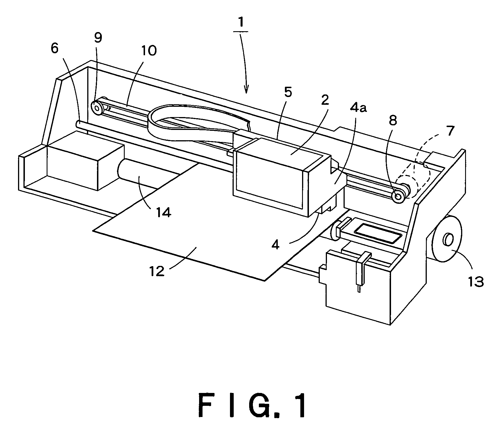
[0132]FIG. 1 is a schematic perspective view of an ink-jetting printer 1 as a liquid ejecting apparatus of a first embodiment according to the invention. The ink-jetting printer 1 includes a carriage 5 supporting a recording head 4 (head member) that has a cartridge holder 4a capable of holding an ink cartridge 2 (liquid container). The carriage 5 is adapted to be reciprocated in a main scanning direction by a head-scanning mechanism.
[0133]The head-scanning mechanism is formed by: a guide bar 6 horizontally extending in a housing, a pulse motor 7 arranged at a right portion of the housing, a driving pulley 8 connected to a rotational shaft of the pulse motor 7, a free pulley 9 mounted at a left portion of the housing, a timing belt 10 connected to the carriage 5 and going around the driving pulley 8 and the free pulley 9, and a controller 11 (see FIG. 6) for controlling the pulse motor 7. Thus, the carriage 5 i.e. the recording head 4 can be reciprocated in the main scanning directi...
second embodiment
[0192]Next, FIG. 9 is a schematic sectional view of a gear pump and periphery thereof in an ink-jetting recording apparatus of a second embodiment according to the invention.
[0193]As shown in FIG. 9, a wetting-agent tank 112 is connected to the pump frame 15f of the gear pump 15g on the side of the capping member 15, via a wetting-agent supplying way 111. An optimum wetting agent is selected for optimally wetting the inside of the gear pump 15g, and the wetting-agent tank 112 is filled with the selected wetting agent.
[0194]Two check valves 113, 114 are provided on the way of the wetting-agent supplying way 111. A priming pump 115 is provided between the two check valves. The priming pump 115 is adapted to operate when the priming pump 115 itself is pushed. When the priming pump 115 operates, the wetting agent is supplied from the wetting-agent tank 112 into the inside of the gear pump 15g.
[0195]In the embodiment, a pushing member 5p for pushing the priming pump 115 is formed on the...
third embodiment
[0220] when the non-operating time Tn of the gear pump 15g is equal to or longer than the standard time Ts, this information is displayed by the displaying part 105. Then, the user can estimate that the inside of the gear pump 15g becomes dry to some extent. Thus, by the user inputting the preliminary-operation instruction into the inputting part 106, the preliminary operation for wetting the inside of the gear pump 15g can be carried out efficiently.
PUM
 Abstract
Description
Claims
Application Information
PatSnap Eureka turns technology decisions into work you can execute. Powered by our Innovation Knowledge Graph, it runs expert workflows across engineering, life sciences, materials and intellectual property. Get your review-ready output in minutes.


