Lubricant structure of engine

a technology of lubricant structure and engine, which is applied in the direction of lubricant mounting/connection, lubrication elements, pressure lubrication, etc., can solve the problems of increased crankshaft agitation resistance, insufficient use of suctioning ability of oil pump, and reduced workability at the time of exchange, so as to facilitate the exchange of primary oil filters

Active Publication Date: 2010-01-21
KAWASAKI MOTORS LTD
View PDF10 Cites 13 Cited by
  • Summary
  • Abstract
  • Description
  • Claims
  • Application Information

AI Technical Summary

Benefits of technology

[0017]It is an object of the present invention to provide a lubricant structure of a semi-dry sump type engine having a crank case divided in a crankshaft direction, that is, a lubricant structure of an engine capable of easily exchanging primary

Problems solved by technology

It is troublesome to perform an exchange work of the primary oil filters, and hence workability at the time of exchange is lowered.
(1) A pressure change is repeated in the crank chamber in accordance with a volumetric change by raising and lowering a piston. However, with the structure of directly suctioning the oil from the crank chamber, the pressure change in the engine influences over suctioning force of the scavenging pump, a

Method used


Image

  • Lubricant structure of engine
  • Lubricant structure of engine
  • Lubricant structure of engine

Examples


Embodiment Construction

Embodiment of the Present Invention

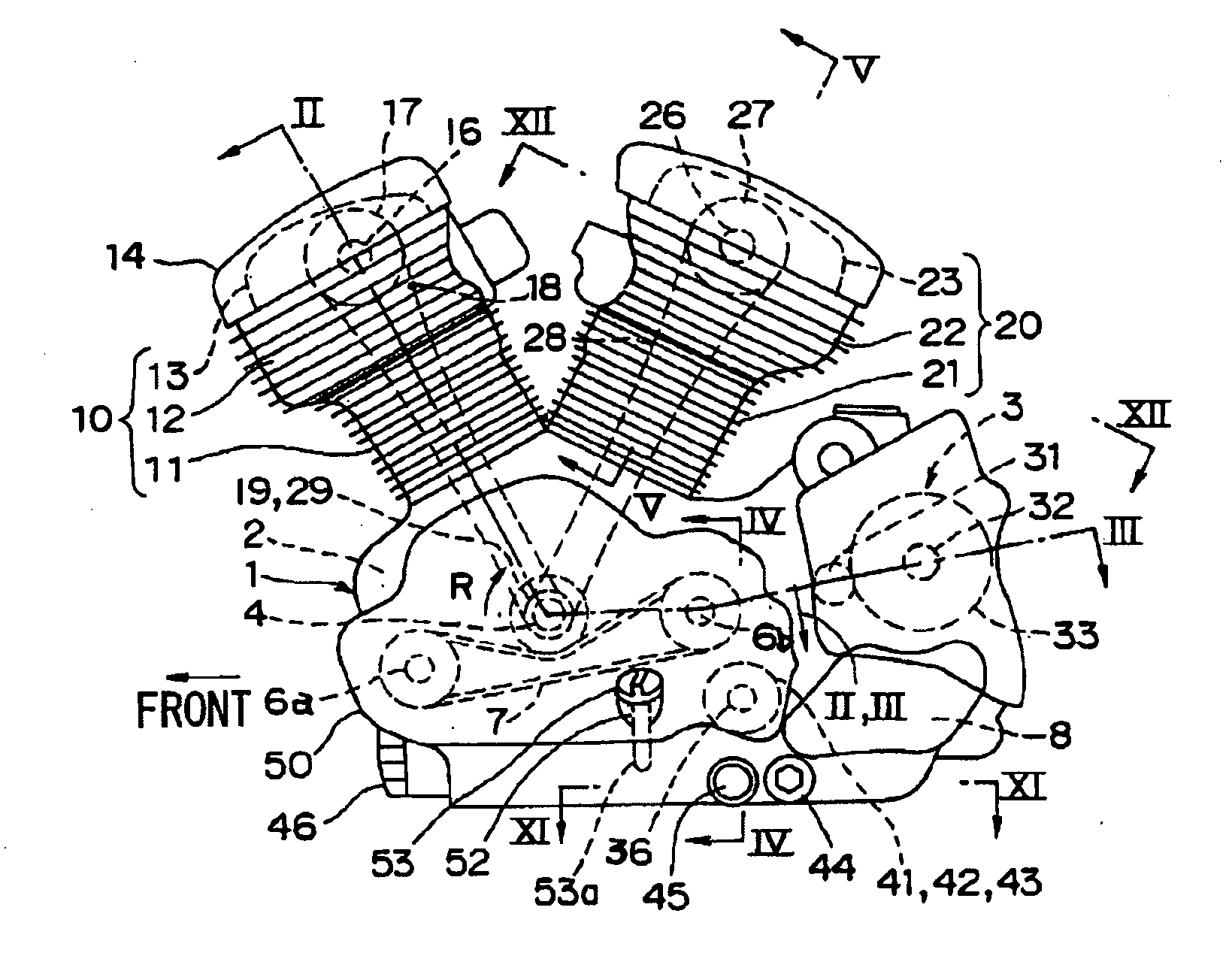
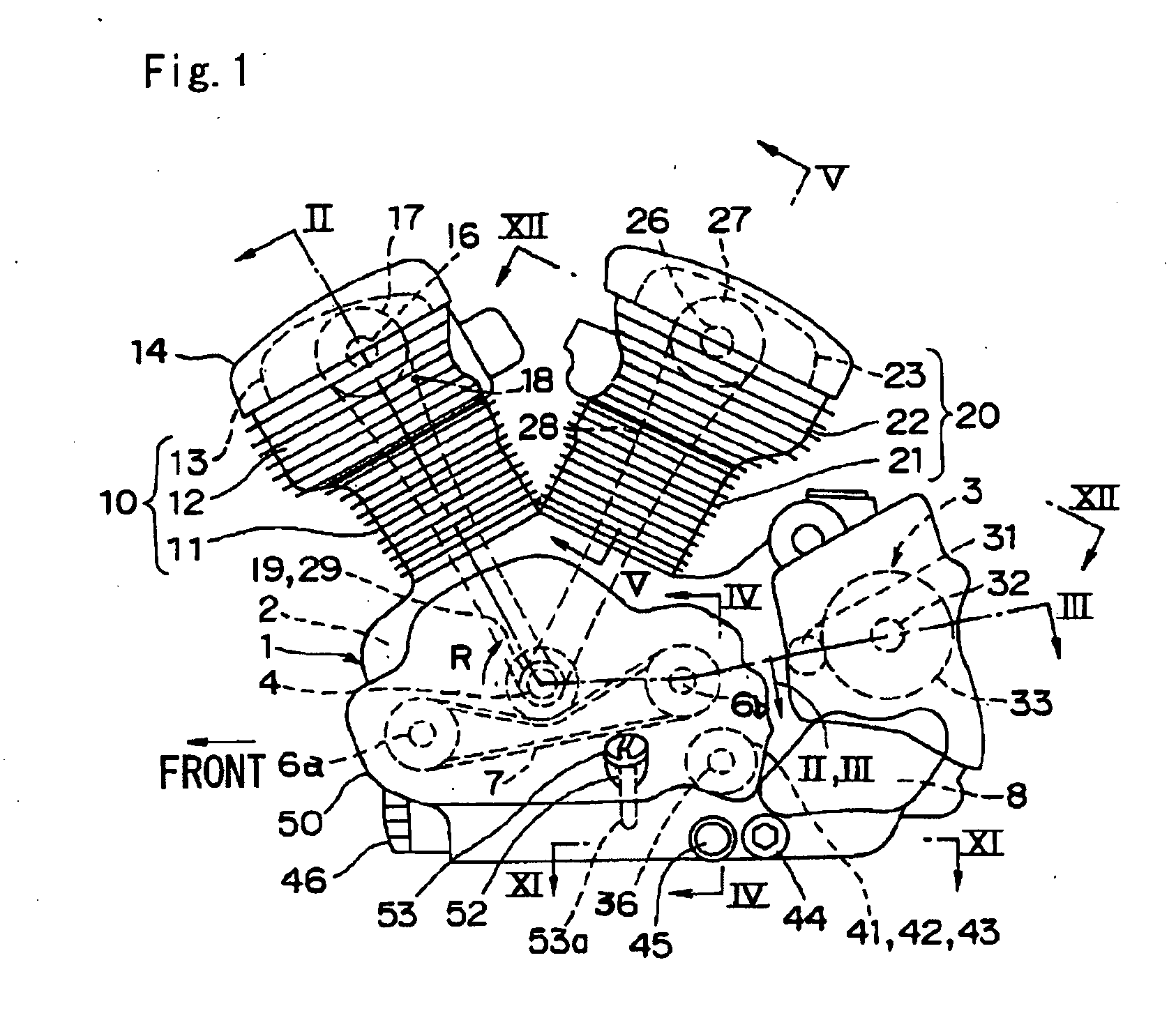
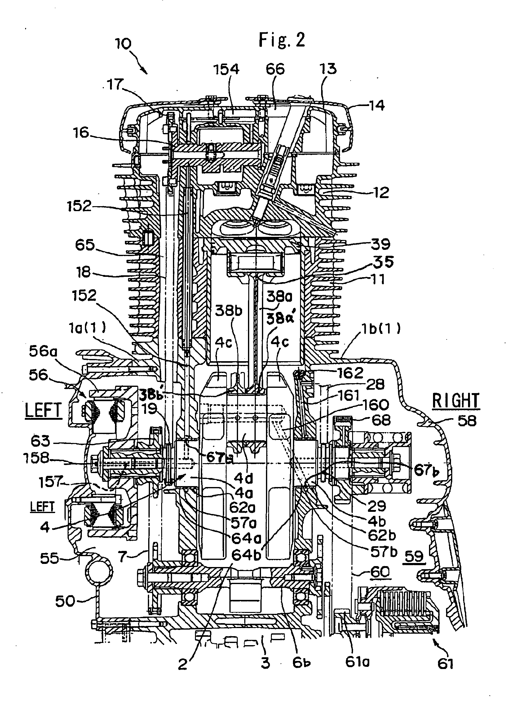
[0091]FIGS. 1 to 14 show a semi-dry sump V-type two-cylinder engine for a two-wheeled motor vehicle provided with a lubricant structure according to the present invention. One embodiment of the present invention will be described based on the above drawings. It should be noted that for convenience of description, hereinafter, a traveling direction of a vehicle is defined as a front side of the engine as shown by an arrow in FIG. 1, and a left and right direction seen from a rider (a crankshaft direction) is defined as a left and right direction of the engine.

(Outline of Entire Engine)

[0092]FIG. 1 is a left side schematic view of the engine, FIG. 2 is an enlarged sectional view taken along line II-II of FIG. 1, FIG. 3 is an enlarged sectional view taken along line III-III of FIG. 1, FIG. 4 is an enlarged sectional view taken along line IV-IV of FIG. 1, and FIG. 5 is an enlarged sectional view taken along line V-V of FIG. 1. In FIG. 1, a front cylind...


PUM


Abstract

The present invention is to provide a lubricant structure of an engine capable of easily and compactly attaching and detaching primary oil filters connected to oil intake sides of two oil pumps to and from a crank case. A power transmission chamber in the crank case dually divided in a crankshaft direction is an oil reserving portion. A first oil pump for pressure-feeding oil of the oil reserving portion to a lubricant point, a second oil pump for returning the oil returned to the crank chamber to the oil reserving portion, and first and second oil filters connected to the oil intake sides of the oil pumps are provided. The first oil filter is inserted from one of left and right crank case members, the second oil filter is inserted from the other crank case member, and both the oil filters are closed by oil filter caps.

Description

BACKGROUND OF THE INVENTION[0001]1. Field of the Invention[0002]The present invention relates to a lubricant structure of an engine, particularly to a lubricant structure suitable for an engine for maintaining a dry state so that oil is not gathered in a crank chamber while driving and also utilizing a power transmission chamber in a crank case as an oil reserving or gathering portion, which is a so-called semi-dry sump type engine.[0003]2. Description of the Prior ArtPrior Art[0004]Unlike a dry sump type engine, there is no need for providing a separate oil tank for a semi-dry sump type engine. Therefore, it is possible to save cost and arrangement space for the oil tank. It should be noted that with another oil pan type engine, there is a problem that a lower side of the engine protrudes and hence engine height is elongated.[0005]In general, the semi-dry sump type engine is provided with two oil pumps. One is a first oil pump for pressure-feeding oil from an oil reserving portion ...

Claims


Application Information

Patent Timeline
IPC IPC(8): F01M11/03F01M1/10
CPCF01M1/12F01M11/03F01M2011/0083F01M2011/0029F01M2011/007F01M2001/126
Inventor ASAYA, NORIKAZU
Owner KAWASAKI MOTORS LTD
Why Eureka
Try Eureka