Link actuating device

a technology of actuating device and link, which is applied in the direction of mechanical control device, gearing, instruments, etc., can solve the problems of increasing the size of the whole mechanism, the weight of the tool mounted on the travelling plate, and the bulkyness of the apparatus, etc., to achieve precise and wide operating range and long bearing life

Active Publication Date: 2014-10-16
NTN CORP
View PDF7 Cites 11 Cited by
  • Summary
  • Abstract
  • Description
  • Claims
  • Application Information

AI Technical Summary

Benefits of technology

[0010]An object of the present invention is to provide a link actuating device which can, despite its compactness in size, operate in a precise and wide operating range and realize long lives of bearings provided in the revolute pair sections.

Problems solved by technology

Accordingly, a problem has been found that the dimensions of the mechanism as a whole increase and the apparatus tends to be bulky in size.
For this reason, there has also been a problem that the weight of a tool mounted on the travelling plate, that is, the weight capacity of the travelling plate, is limited to a small value.
For these reasons, it is difficult to use the parallel link mechanism in a medical device or the like which requires the parallel link mechanism to be compact in size and to operate in a precise and wide operating range.

Method used


Image

  • Link actuating device
  • Link actuating device
  • Link actuating device

Examples


first embodiment

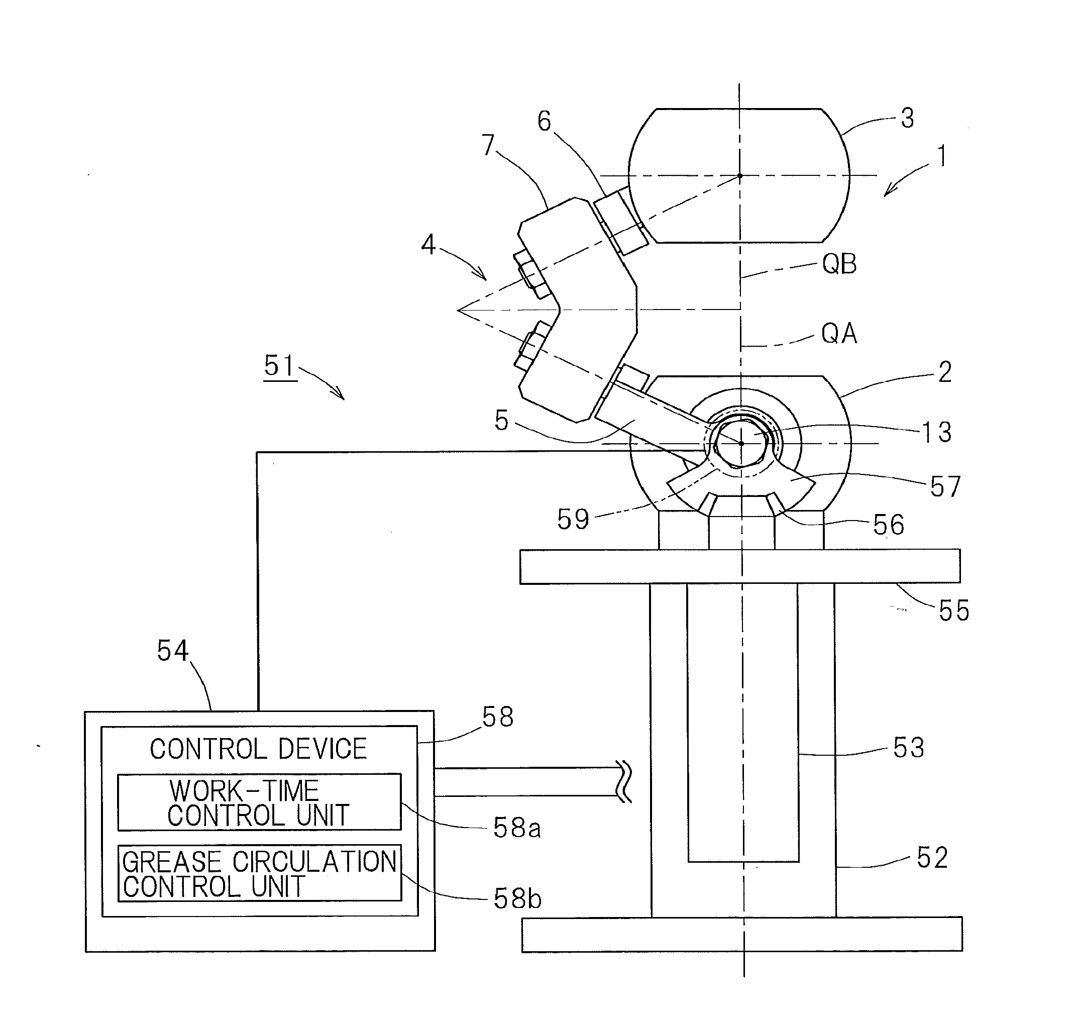
[0041]A link actuating device according to the present invention will be described with reference to FIG. 1 to FIG. 9. As shown in FIG. 1, this link actuating device 51 includes a parallel link mechanism 1, a base 52 which supports the parallel link mechanism 1, two or more actuators 53 which cause the parallel link mechanism 1 to operate, and a control device 58 which controls these actuators 53. In this example, the control device 58 is provided in a controller 54, but the control device 58 may be provided separately from the controller 54.

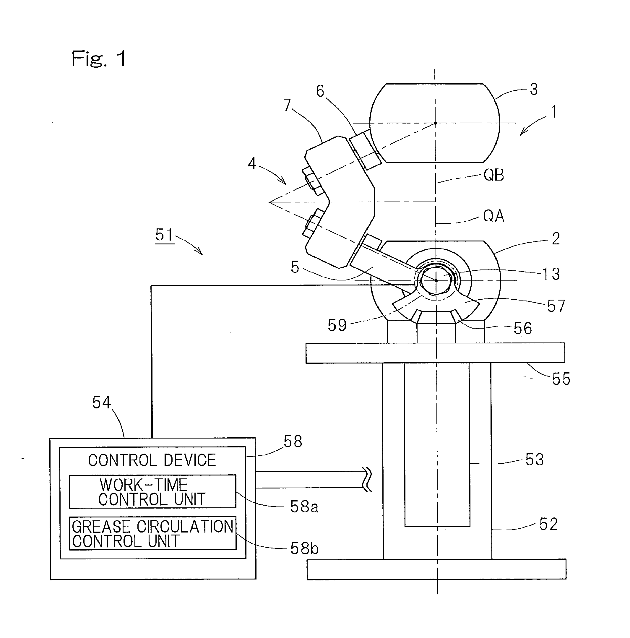
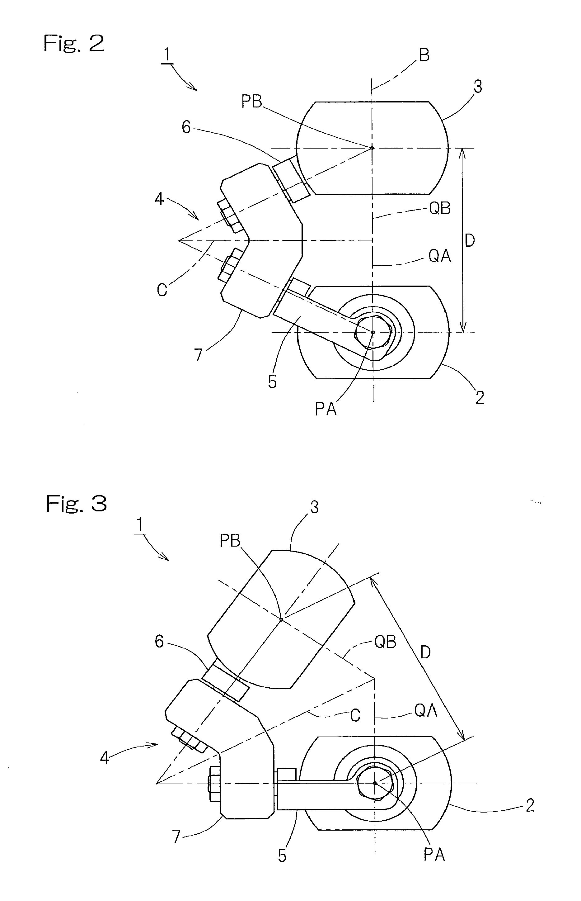
[0042]At first, the parallel link mechanism 1 is described. FIG. 2 and FIG. 3 are front views respectively showing different states of the parallel link mechanism. The parallel link mechanism 1 is of a type in which a distal end side link hub 3 is connected to a proximal end side link hub 2 via three link mechanisms 4 such that alteration in posture is allowed. FIG. 2 and FIG. 3 show only one link mechanism 4.

[0043]FIG. 4 is a perspective view s...

second embodiment

[0080]FIG. 11 and FIG. 12 show the present invention in which a different type of the parallel link mechanism is used. This parallel link mechanism 1 has the bearings 12 (FIG. 12), of an outer ring rotation type, which rotatably support each proximal side end link member 5 relative to the proximal end side link hub 2 and each distal side end link member 6 relative to the distal end side link hub 3. The revolute pair section between the proximal end side link hub 2 and the proximal side end link member 5 is explained as an example. As shown in FIG. 12, the proximal end side link hub 2 has shaft portions 25 formed at three positions in the circumferential direction thereof. The double row bearings 12 have inner rings (not shown) mounted on the outer periphery of each shaft portion 25, and outer rings (not shown) mounted on the inner periphery of a communication hole 26 formed in each proximal side end link member 5. Through fastening with a nut 27 threadedly engaged on a distal end sc...

third embodiment

[0082]FIG. 13 to FIG. 15 show a link actuating device according to the present invention. In FIG. 13, this link actuating device 61 is of a type in which a distal end mounting member 63, on which a various type of instrument or the like is mounted, is connected to a base 62 via the parallel link mechanism 1 shown in FIG. 11 and FIG. 12, such that alteration in posture is allowed. Between the base 62 and the proximal end side link hub 2 of the parallel link mechanism 1, a spacer 64 is interposed.

[0083]As shown in FIG. 14 and FIG. 15 being a partial enlarged view of FIG. 14, at least two of the three link mechanisms 4 of the parallel link mechanism 1 are each provided with an actuator 70 which arbitrarily alters the posture of the distal end side link hub 3 relative to the proximal end side link hub 2 by rotating its corresponding proximal side end link member 5, and a reduction gear unit 71 which transmits the amount of operation of the actuator 70 to the proximal side end link membe...


PUM


Abstract

A bearing is interposed in the revolute pair between a proximal end side link hub (2) and each proximal side end link member (5). A control device controls an actuator, to perform work-time control for causing a determined work operation to be executed and to perform, while the work-time control is stopped, grease circulation control for circulating grease sealed in the bearing. The maximum value θmax of a bending angle in the work-time control does not exceed the maximum allowable bending angle θ′max being the maximum value of the bending angle allowable in the mechanism, and the maximum value of the bending angle in the grease circulation control is greater than the maximum value θmax of the bending angle in the work-time control and smaller than the maximum allowable bending angle θ′max.

Description

CROSS REFERENCE TO THE RELATED APPLICATION[0001]This application is based on and claims Convention priority to Japanese Patent Application No. 2011-243463, filed Nov. 7, 2011, the entire disclosure of which is herein incorporated by reference as a part of this application.BACKGROUND OF THE INVENTION[0002]1. Field of the Invention[0003]The present invention relates to a link actuating device which is used in a device such as a medical device, an industrial device, or the like which is required to operate in a precise and wide operating range in a three-dimensional space.[0004]2. Description of Related Art[0005]One example of a working device equipped with a parallel link mechanism is disclosed in Patent Document 1, and one example of a link actuating device used in a medical device, an industrial device, or the like is disclosed in Patent Document 2.Prior Art Document[0006][Patent Document 1] JP Laid-open Patent Publication No. 2000-94245[0007][Patent Document 2] U.S. Pat. No. 5,893,...

Claims


Application Information

Patent Timeline
Patent Type & Authority Applications(United States)
IPC IPC(8): F16H21/46
CPCF16H21/46F16C33/6625F16H57/0445F16H57/0471F16C19/06F16C19/22B25J9/0048B25J9/108B25J19/0062B25J19/0066Y10T74/20207
Inventor YAMADA, HIROYUKIISOBE, HIROSHISONE, KEISUKE
Owner NTN CORP
Why Eureka
Try Eureka