Rolling bearing device

Inactive Publication Date: 2012-12-27
NTN CORP
View PDF9 Cites 17 Cited by
  • Summary
  • Abstract
  • Description
  • Claims
  • Application Information

AI Technical Summary

Benefits of technology

[0026]According to the rolling bearing device of the present invention, the absolute amount of the lubricating oil that contributes to the lubrication can be increased without increasing the number of components

Problems solved by technology

In the above-mentioned rolling bearing device to be used in a low-temperature, high-speed rotation environment or

Method used


Image

  • Rolling bearing device
  • Rolling bearing device
  • Rolling bearing device

Examples


Example

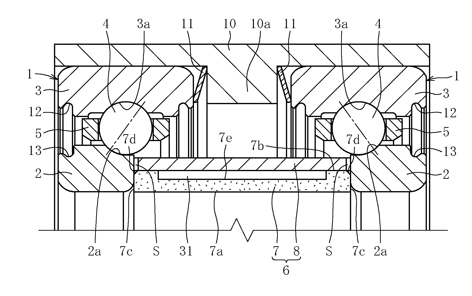
[0036]A rolling bearing device illustrated in FIG. 1 is applicable as a bearing for a liquid fuel turbopump of a rocket engine, which is to be used in a low-temperature, high-speed rotation environment, and the rolling bearing device comprises double row angular contact ball bearings 1. The angular contact ball bearings 1 comprise a pair of inner races 2 fixed by fitting to a shaft on a rotational side (20: see FIGS. 7 and 8), and a pair of outer races 3 fixed by fitting to an inner peripheral surface of an outer race spacer 10. In each angular contact ball bearing 1, a plurality of rolling elements 4 are arranged at a contact angle between a raceway surface 2a of the inner race 2 and a raceway surface 3a of the outer race 3, and a retainer 5 retains the rolling elements 4 at regular intervals in a circumferential direction thereof.

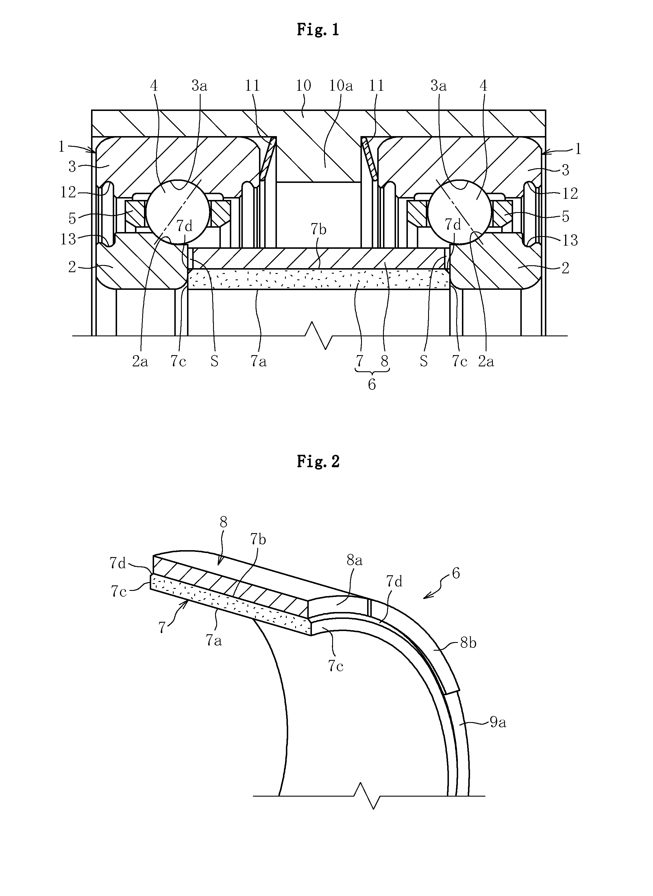
[0037]An inner race spacer 6 is installed between the pair of inner races 2. The inner race spacer 6 has a cylindrical shape, and both end surfaces there...


PUM


Abstract

Provided is a rolling bearing device comprising inner races (2), outer races (3), rolling elements (4), a retainer (5), and an inner race spacer (6). The inner race spacer (6) is formed of an oil reservoir member (7) made of a sintered metal impregnated with lubricating oil, and a spacer cover (8) fitted onto an outer periphery of the oil reservoir member (7). Through a centrifugal force to be applied to the oil reservoir member (7) at the time of bearing rotation, the lubricating oil is scattered radially outward through a chamfered portion (7d) of the oil reservoir member (7) via an oil supply passage (S), to thereby lubricate the interior of the bearing with oil.

Description

TECHNICAL FIELD[0001]The present invention relates to a rolling bearing device to be used in an environment in which a general fluid lubricant (for example, grease) cannot be employed, and more particularly, to a rolling bearing device comprising an inner race spacer.BACKGROUND ART[0002]As a bearing device to be used for a liquid fuel turbopump of a rocket engine in a low-temperature, high-speed rotation environment and a rolling bearing device to be used for a space apparatus in a vacuum environment, a double row angular contact ball bearing is used in some cases. In this bearing device, angular contact ball bearings are arranged in two rows on an outer peripheral surface of a main shaft serving as a rotation shaft, and in many cases, an inner race spacer and an outer race spacer are mounted between the double row angular contact ball bearings to perform axial positioning of inner races and outer races.[0003]In the above-mentioned rolling bearing device to be used in a low-temperat...

Claims


Application Information

Patent Timeline
IPC IPC(8): F16C33/66
CPCF16C19/184F16C25/083F16C33/303F16C33/6611F16C33/6677F16C19/543F16C33/6648F16C35/077F16C19/163F16C19/548F16C2326/47
Inventor ITO, DAICHINAKAMURA, TOMOYAFUJIKAKE, YASUHITO
Owner NTN CORP
Why Eureka
Try Eureka