Non-rotating shaft for a continuous casting machine

Inactive Publication Date: 2011-02-03
AB SKF
View PDF4 Cites 0 Cited by
  • Summary
  • Abstract
  • Description
  • Claims
  • Application Information

AI Technical Summary

Benefits of technology

[0009]An effect of the invention is that by this configuration of the non-rotating shaft, the osculation between the mechanical element and the non-rotating shaft is improved. This is achieved by the configuration of the portion, which increases the contact zone between the non-rotating shaft and the mechanical element. Thus, when the non-rotating shaft supports a bearing arrangement, the invention increases the bearing life, and permits a good ability to mount and dismount the bearing arrangement onto the non-rotating shaft. Another advantage is that the invention leads to an increased load capacity of the bearing arrangement, and permits a good ability to mount and dismount the bearing arrangement onto the non-rotating shaft.
[0010]In an embodiment of the non-rotating shaft, the distance between any point of the portion and a center of the circular cross-section is maximum 10 percent s

Problems solved by technology

It is well known that bearings have shorter bearing life when used in harsh environments.
Furthe

Method used


Image

  • Non-rotating shaft for a continuous casting machine
  • Non-rotating shaft for a continuous casting machine
  • Non-rotating shaft for a continuous casting machine

Examples


Example

DETAILED DESCRIPTION OF THE DRAWINGS

[0058]It should be understood that some features in the figures are exaggerated in order to clarify the inventive idea.

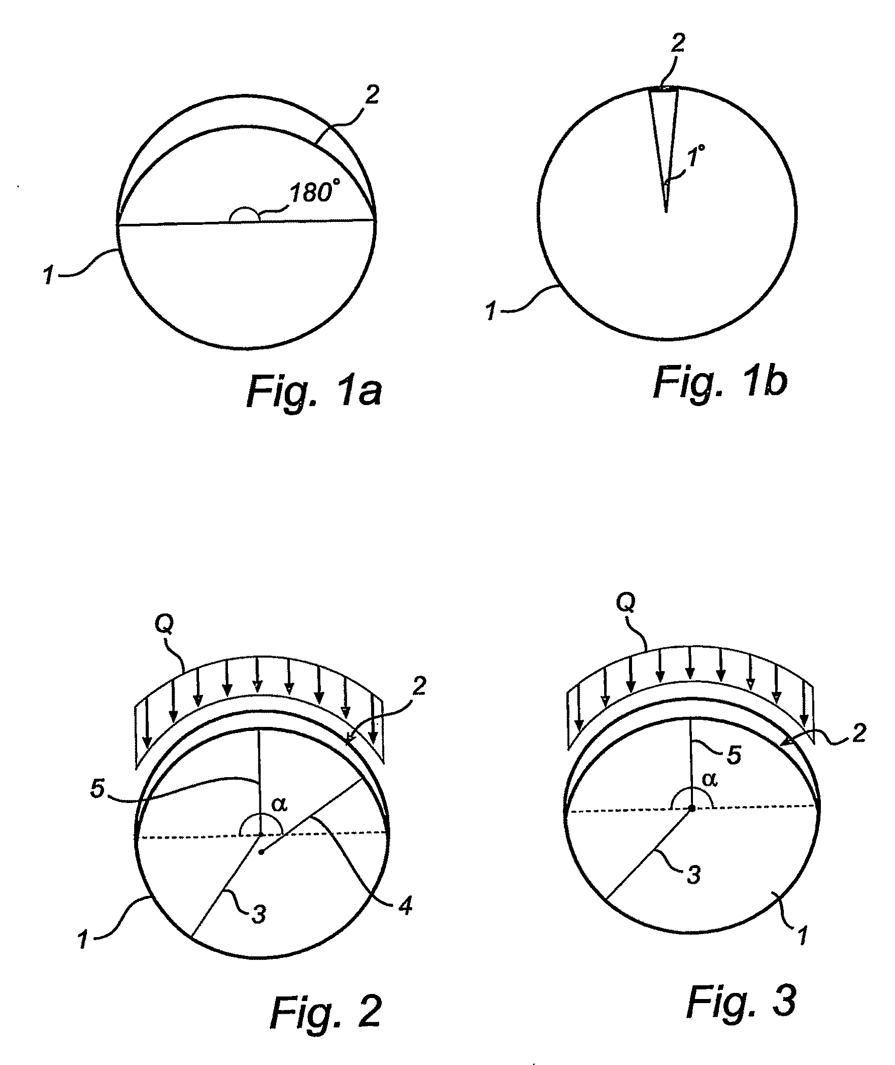
[0059]In FIG. 1a and 1b, two embodiments of a cross-section of a non-rotating shaft 1 according to the invention are disclosed. It shows that the non-rotating shaft 1 may be designed to have different angles in the interval of the portion 2. In FIG. 1a, the portion 2 has an angle in the interval, which in this embodiment is 180 degrees. In FIG. 1b, the portion 2 has an angle in the interval, which in this embodiment is 1 degree. In a preferred embodiment, the angle is 180 degrees. It should be understood that the claimed invention could have any other angle in the interval 1 to 180 degrees.

[0060]In FIG. 2, a cross-section of another embodiment of a non-rotating shaft 1 according to the invention is disclosed. It comprises a radius 3 of the circular cross-section and a portion 2. In this embodiment, the portion 2 is in the shape of...


PUM

PropertyMeasurementUnit
Lengthaaaaaaaaaa
Fractionaaaaaaaaaa
Angleaaaaaaaaaa

Abstract

The invention comprises a non-rotating shaft for supporting a mechanical element of a roll segment in a continuous casting machine, having an essentially circular cross-section. The circular cross-section presents a portion having a smooth peripheral, wherein the distance between any point of the portion and a center of the circular cross-section is shorter than a radius of the circular cross-section. Furthermore, the circular cross-section presenting the portion extends axially, which defines a section of the shaft meant to a least partly receive the mechanical element, and the section of the shaft is meant to receive a load at least partly at the portion. In addition, according to a second aspect, the invention comprises a segment roll for a continuous casting machine, which comprises the non-rotating shaft according to the first aspect.

Description

FIELD OF THE INVENTION[0001]According to a first aspect, the invention concerns a non-rotating shaft for supporting a mechanical element of a roll segment in a continuous casting machine. According to a second aspect, the invention concerns a segment roll for a continuous casting machine having a non-rotating shaft.BACKGROUND OF THE INVENTION[0002]It is well known that bearings have shorter bearing life when used in harsh environments. This applies to bearings used in continuous casting machines. The continuous casting process is characterized by high loads on the rollers of the segment rolls, on which the slab, billet, bloom or beam blank runs. Furthermore, the process is characterized by high temperatures, high humidity, high contamination etc. A number of segment roll designs have been proposed. One such segment roll is introduced in EP1537927, which describes the configuration of a segment roll with a non-rotating shaft supporting a number of roll segments. EP1537927 provides a ...

Claims


Application Information

Patent Timeline
IPC IPC(8): B22D11/053
CPCB22D11/1287Y10T74/2116Y10T74/211F16C13/02F16C2322/00F16C3/02
Inventor AXELSSON, MAGNUSCOSTA, PATRIK
Owner AB SKF
Why Eureka
Try Eureka