Rolling bearing

a rolling bearing and oil-lubricated technology, applied in the direction of rolling contact bearings, rotary bearings, shafts and bearings, etc., can solve the problems of loss of sealing capability, increase manufacturing costs, limit the extent to which the dimensional accuracy of the elastic seal member, which is formed from an elastic material, can be improved, etc., to prevent impairment of sealability, prolong the life of the seal device, and improve the durability of the seal devi

Active Publication Date: 2016-04-21
NTN CORP
View PDF0 Cites 18 Cited by
  • Summary
  • Abstract
  • Description
  • Claims
  • Application Information

AI Technical Summary

Benefits of technology

[0050]According to the present invention, since the seal device includes a ring member made of a metal or a resin and formed with through holes, it is resistant to deformation under an external force compared to a conventional elastic seal member comprising an elastomer only. Thus, the seal device can be secured to a bearing race, which prevents impairment of sealability, improves durability of the seal device, and extends its life.
[0051]According to this invention, since a lip made of a relatively soft material such as an elastomer is joined to a ring member integrally formed with a filter, the ring member can be securely fixed to one of the bearing races, so that the filter can perform its function over a prolonged period of time, while the lip can maintain high sealability between the lip and the other bearing race.
[0052]Since the ring member, which is made of a relatively hard material, is fitted to one of the bearing races, while the soft lip is not directly fixed to the other bearing race, it is not necessary to control the dimensions of the member made of a soft material such as an elastomer as strictly as in conventional arrangements. Since the ring member is resistant to deformation under an external force, even if the bearing is used in a harsh environment in which foreign substances tend to mix into lubricating oil, the seal device can reliably prevent entry of foreign substance harmful to the bearing into the bearing over a prolonged period of time, and thus prolong the life of the bearing.

Problems solved by technology

Thus, if a larger-than-expected external force is applied to the elastic seal member while, for example, assembling the bearing, during transportation of the bearing, or when mounting the bearing into machinery, the elastic seal member could be elastically deformed, or moved out of the correct mounting position, thus losing its sealing capability.
However, since the elastic seal member is directly mounted to the bearing, in order to further improve the accuracy of the interference, it is necessary to further improve the accuracy of the dimensions of the elastic seal member and the bearing, which, however, adds to the manufacturing cost.
Also, there is a limit to the extent to which the dimensional accuracy of the elastic seal member, which is formed from an elastic material, can be improved.

Method used


Image

  • Rolling bearing
  • Rolling bearing
  • Rolling bearing

Examples


first embodiment

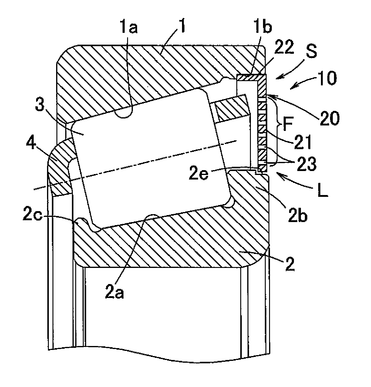
[0072]FIG. 1 shows a partial enlarged sectional view of a rolling bearing 10 according to the present invention. The rolling bearing 10 includes an outer bearing race 1, an inner bearing race, and rolling elements 3 in the form of tapered rollers mounted in the bearing space defined between the outer bearing race 1 and the inner bearing race 2. The rolling elements 3 are received between a large flange 2b and a small flange 2c of the inner bearing race 2, and are retained in position in the circumferential direction by a retainer 4. The inner bearing race 2 and the outer bearing race 1 has raceways 2a and 1a, respectively, which are arranged such that the distance therebetween decreases from one axial end (right-hand side in FIG. 1) toward the other axial end (left-hand side in FIG. 1).

[0073]A seal device S is mounted to one of the openings of the bearing space of the rolling bearing 10 at its respective axial ends. The seal device S comprises a metal ring member 20 formed with thro...

second embodiment

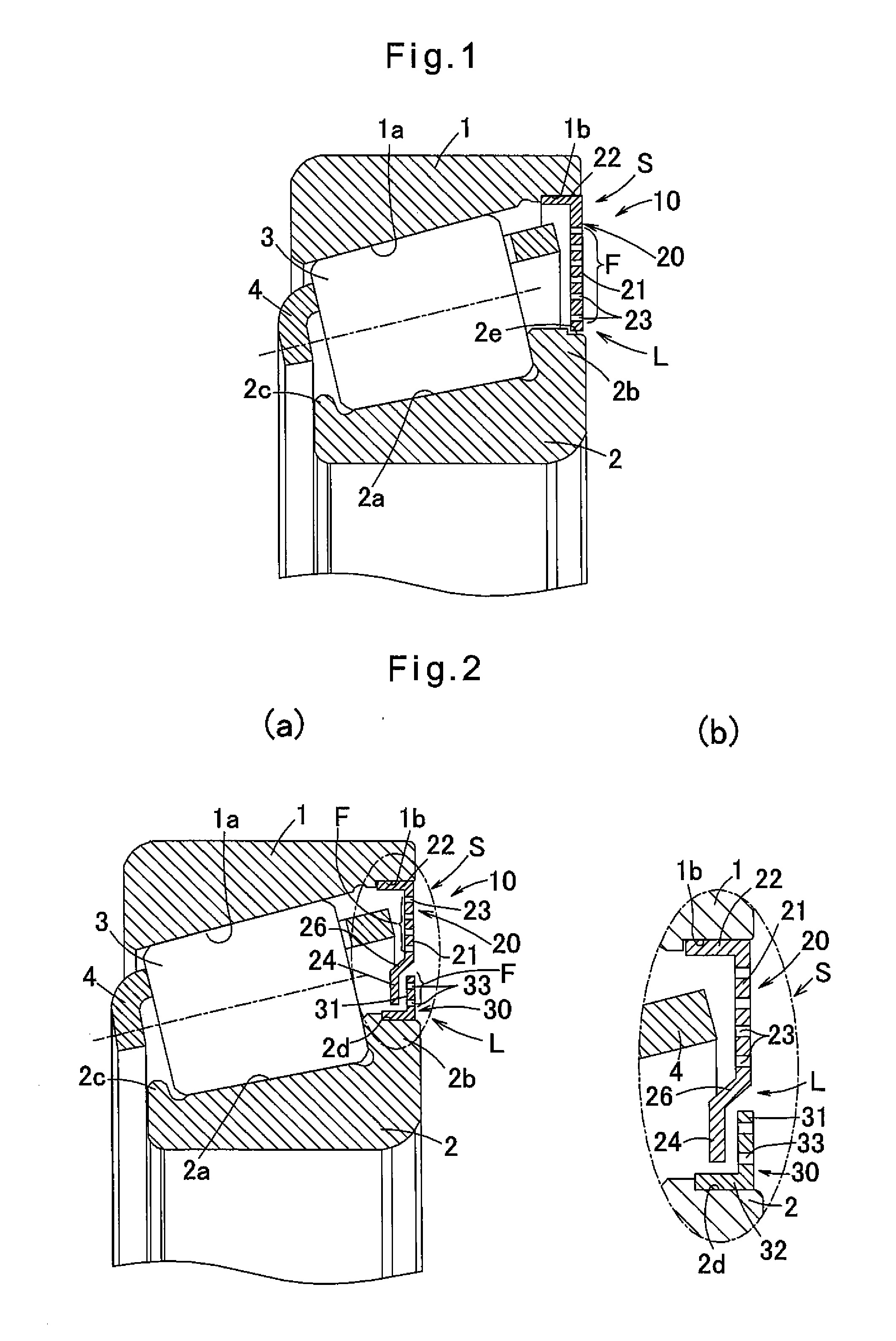
[0080]As shown in FIG. 2(a), the seal device S of the second embodiment includes a ring member 20 constituted by a fitting portion 22 fitted in a fitting recess 1b formed in the outer bearing race 1 with an interference fit, and a side portion 21 extending radially inwardly from the fitting portion 22 so as to be integral with the fitting portion 22. The seal device S further includes a sub-ring member (auxiliary ring member) 30 constituted by a fitting portion 32 fitted in a fitting recess 2d formed in the inner bearing race 2 with an interference fit, and a side portion 31 extending radially outwardly from the fitting portion 32 so as to be integral with the fitting portion 32.

[0081]The ring member 20 also has a relief portion 24 at the radially inner edge thereof. The relief portion 24 is a plate-shaped portion having surfaces extending parallel to the surfaces of the side portion 21, and slightly displaced toward the rolling elements 3 from the side portion 21. The relief portio...

fourth embodiment

[0097]The pull-out prevention means of the fourth embodiment may be used in any other embodiments.

[0098]FIG. 5(a) shows a rolling bearing 10 according to the fifth embodiment of the present invention, and FIG. 5(b) shows a modification of the fifth embodiment.

[0099]The fifth embodiment includes, as with the fourth embodiment, an axial pull-out prevention means provided between the ring member 20 and the stationary, outer bearing race, and another axial pull-out prevention means provided between the sub-ring member 30 and the rotatable, inner bearing race.

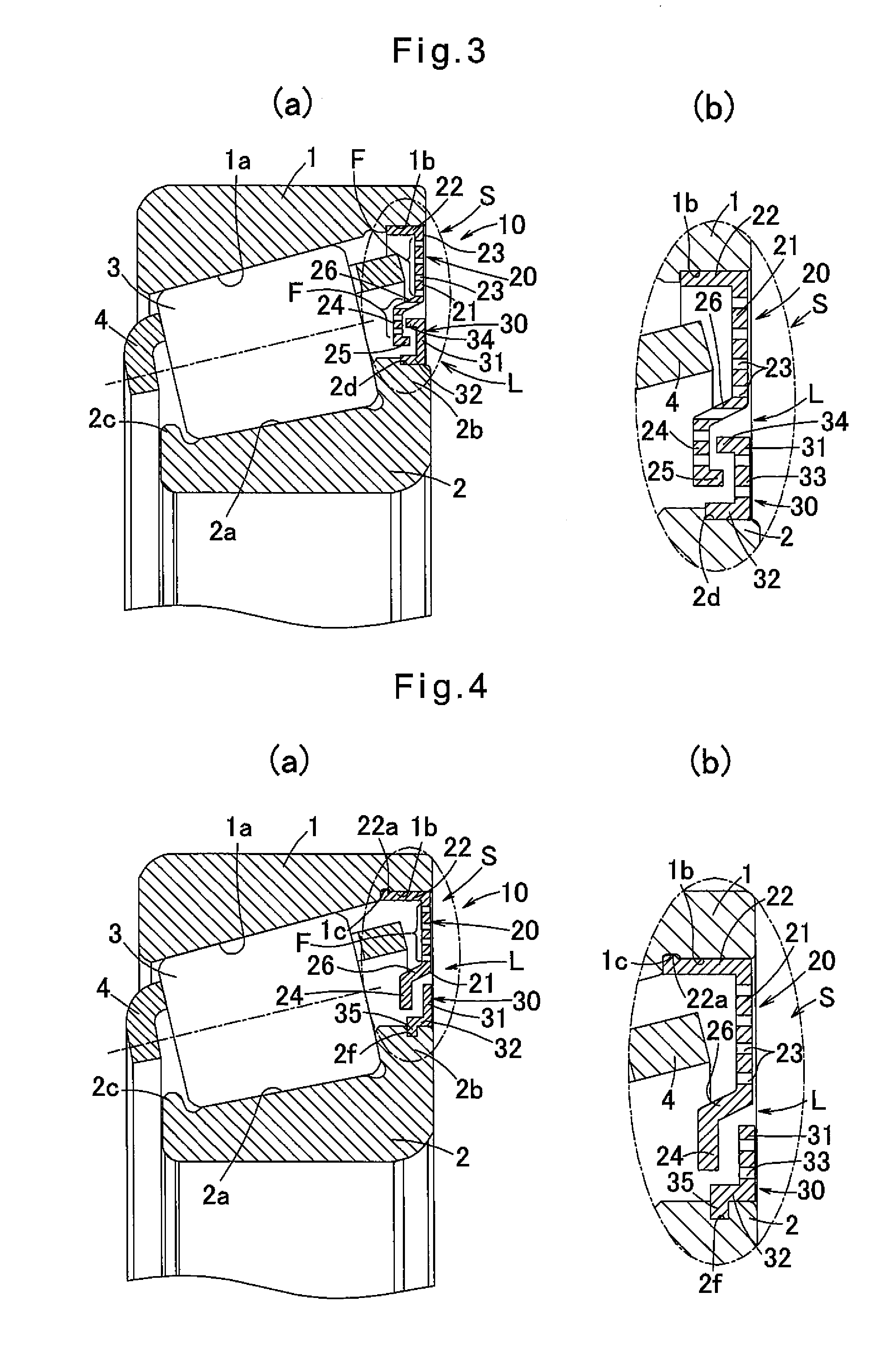
[0100]In this embodiment, the ring member 20 includes a fitting portion 22 fitted in a fitting recess 1e formed in the outer surface of the outer bearing race 1 with an interference fit, and a side portion 21 integral with the fitting portion 22 and extending radially inwardly from the fitting portion 22. This ring member 20 also includes the relief portion 24 and the connecting portion 26 used in the previous embodiments.

[0101]The ...


PUM


Abstract

A rolling bearing includes an outer bearing race and an inner bearing race defining a bearing space therebetween. Rolling elements are mounted in the bearing space. A seal device is provided at one axial opening of the bearing space and includes a ring member formed of a metal and formed with through holes configured such that lubricating oil can pass through the through holes and solid foreign substances cannot pass through the through holes. One of the outer bearing race and the inner bearing race is stationary, and the other is rotatable. The ring member is in engagement with the stationary bearing race. A sub-ring member, which is a separate member from the ring member and made of a metal, is fixed to the rotatable bearing race. Between the ring member and the sub-ring member, a gap is defined which constitutes a labyrinth seal structure.

Description

TECHNICAL FIELD[0001]This invention relates to an oil-lubricated rolling bearing, and particularly a rolling bearing configured to be lubricated by oil which flows into the bearing through a filter capable of preventing entry of foreign substances in the lubricating oil.BACKGROUND ART[0002]Rolling bearings are mounted in power transmission mechanisms, such as transmissions, differentials and speed reducers, of transportation machinery such motor vehicles, and of construction machinery, travel units including the above-mentioned power transmission mechanisms, hydraulic pumps, and in various other industrial machinery.[0003]Foreign substances such as wear dust (such as iron dust) from gears tend to be mixed into oil used to lubricate the above-mentioned rolling bearings, especially where the oil is used to lubricate both such rolling bearings and a power transmission mechanism.[0004]If foreign substance infiltrate into a rolling bearing, they tend to get stuck between components of th...

Claims


Application Information

Patent Timeline
Patent Type & Authority Applications(United States)
IPC IPC(8): F16C33/66F16C33/78F16C33/80F16C19/36
CPCF16C33/667F16C19/364F16C33/80F16C33/7866F16C33/7846F16C33/726F16C33/7813F16C33/7816F16C33/7873F16C33/7876F16C33/7879F16C33/7886F16C43/045F16C2240/44F16C2240/46F16C33/7863
Inventor MIYAZAKI, HIROYUKIYAMAUCHI, KIYOSHIGEKOSAKA, YORIKOKISHIDA, HISA
Owner NTN CORP
Why Eureka
Try Eureka