Pressure lubrication system for countershaft transmission

Inactive Publication Date: 2001-03-27
EATON CORP
View PDF6 Cites 14 Cited by
  • Summary
  • Abstract
  • Description
  • Claims
  • Application Information

AI Technical Summary

Benefits of technology

The present invention allows for forced lubrication of wear parts within a transmission that readily degrade within a high torque transmission absent such lubrication. In particular, lubricating the front

Problems solved by technology

In particular, lubricating the front countershaft bearin

Method used


Image

  • Pressure lubrication system for countershaft transmission
  • Pressure lubrication system for countershaft transmission
  • Pressure lubrication system for countershaft transmission

Examples


Embodiment Construction

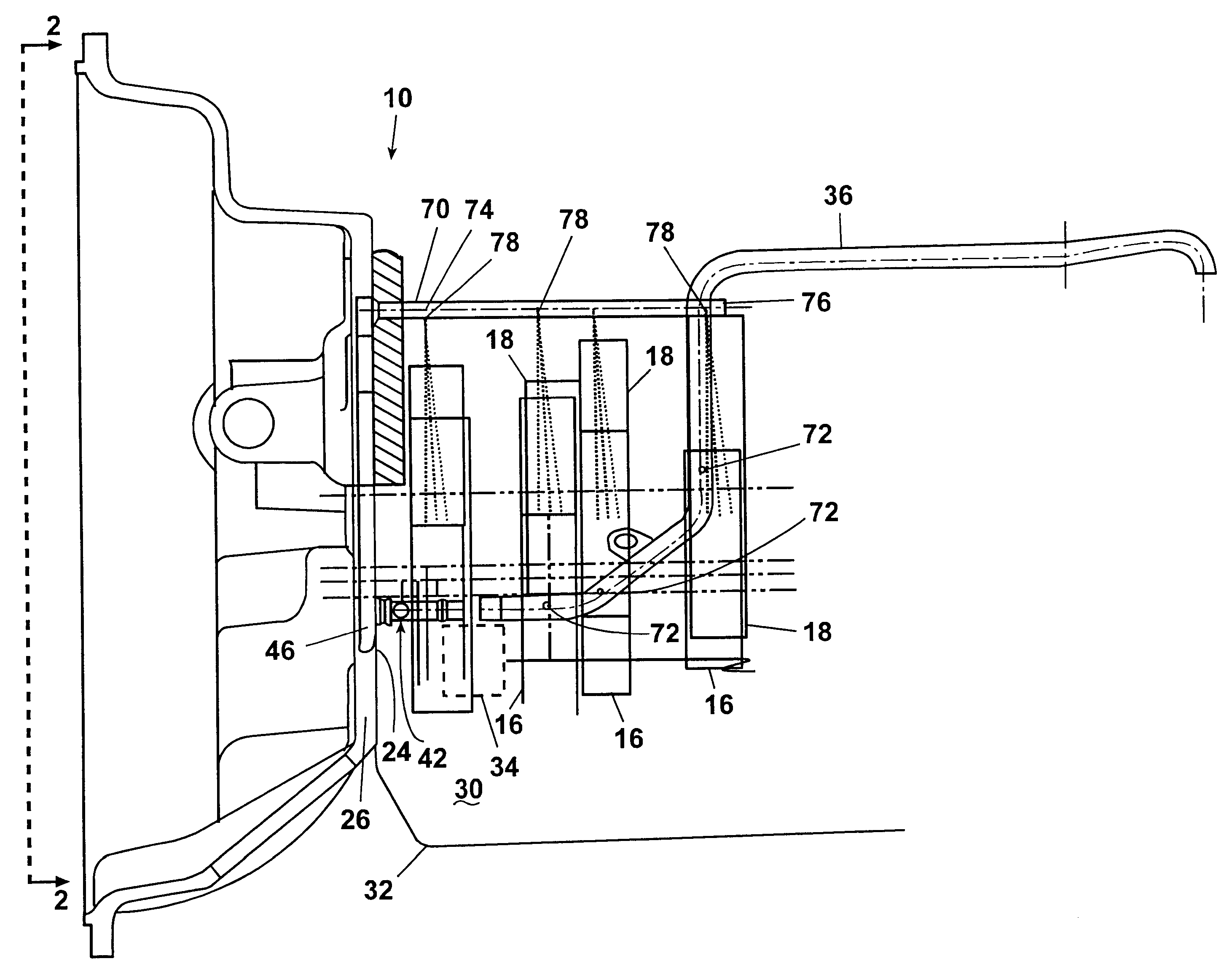
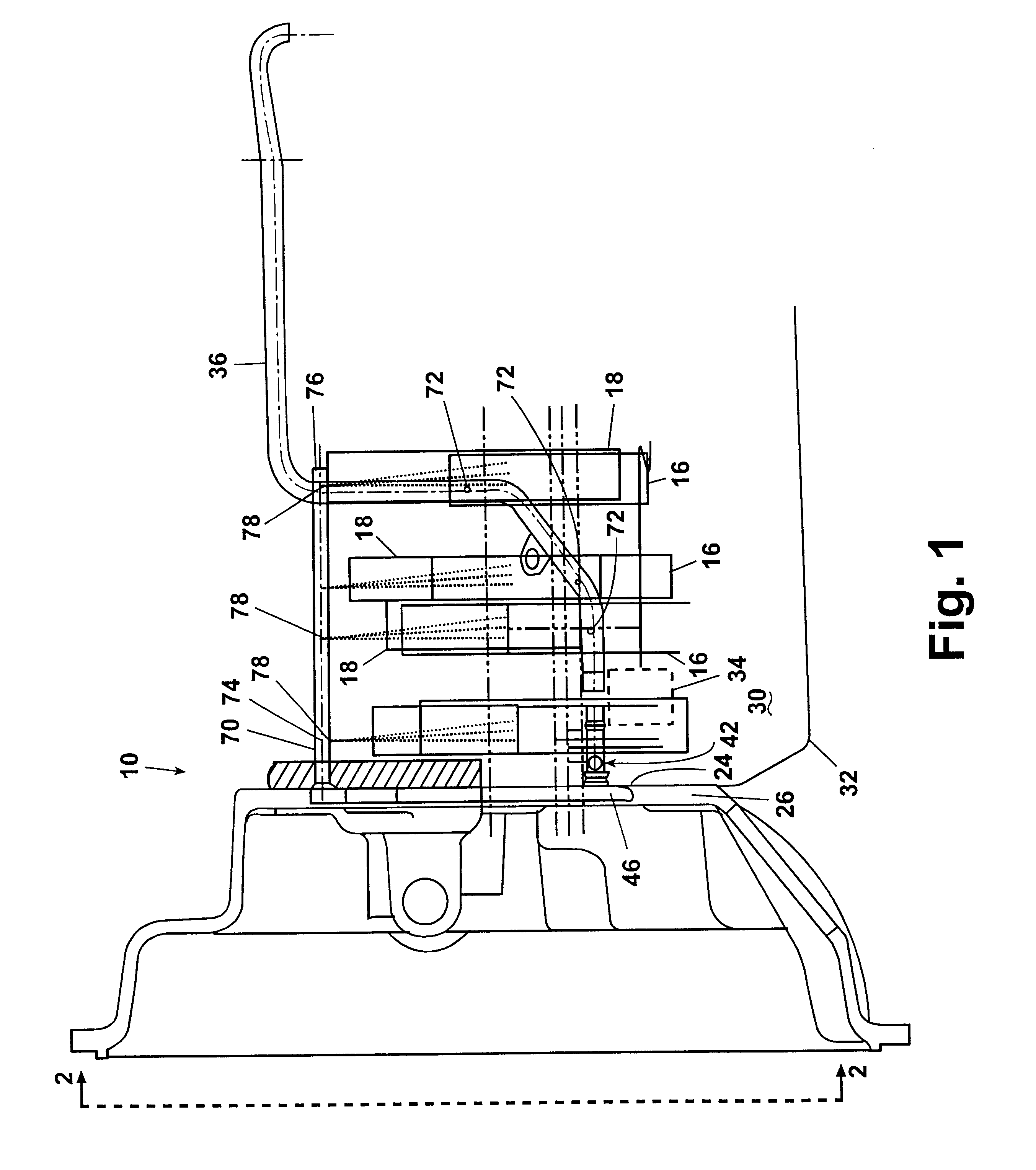
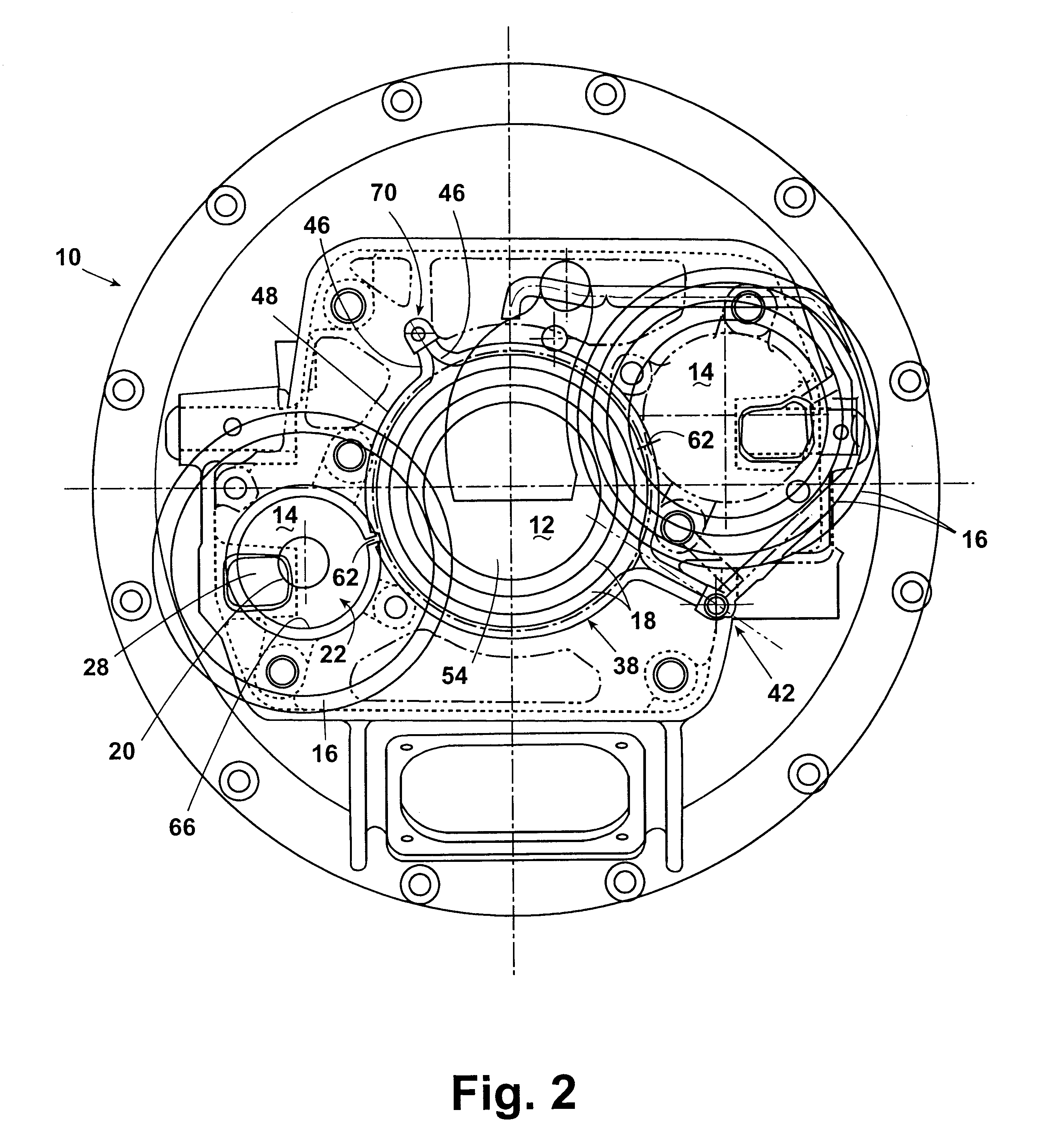
A countershaft transmission 10, such as the one shown diagrammatically in FIGS. 1 and 2, generally include a main shaft 12 having two or more similar countershafts 14 arranged at equally spaced intervals about the main shaft 12. The countershafts 14 include similarly placed countershaft gears 16 arranged respectively opposite each other on the countershafts 14 that engage respective main shaft gears 18 placed about the main shaft 12. The main shaft gears 18 are in constant engagement with respective countershaft gears 16. The main shaft 12 is selectively clutchable to one of the main shaft gears 18. In general, several main shaft gears are provided to allow selective clutching between main shaft gears having different gear ratios.

Each countershaft 14 is generally supported at a front end 20 within a pocket 22 machined into a front internal face 24 of a transmission front wall 26. In FIG. 2, two countershafts 14 are shown within respective pockets 22. To minimize friction, the counte...


PUM


Abstract

A lubrication system for transmissions is provided wherein a lubrication flow path is provided from an oil pump located within a transmission casing to front countershaft bearings. A second flow path provides oil directly to a predetermined number of gear sets located along a main shaft. In one embodiment, oil flows through a first tube from the oil pump to an annular ring located in a groove between a front wall of the transmission main case and a rear face of a clutch housing. The ring is provided with a plurality of apertures along its outer circumference spaced to allow oil to flow directly to front bearings of any counter shaft placed adjacent the main shaft. A closed ended tube connects to the annular ring and extends perpendicularly from the annular ring through the front wall of the transmission main case. The closed ended tube extends substantially parallel to the driven main shaft, and includes spaced apertures that deliver oil directly to a predetermined number of gear sets located axially along the main shaft.

Description

FIELD OF THE INVENTIONThe present invention relates to lubrication in mechanical transmissions and in particular to multiple countershaft transmissions wherein means are provided for directly lubricating countershaft bearings and gears within the transmission.BACKGROUND OF THE INVENTIONTransmission systems are a vital link in the powertrain of any vehicle. The purpose of the transmission system is to employ gears of various sizes to provide an engine with a mechanical advantage over the driving wheels. Maintaining lubrication to the moving parts within the transmission helps to ensure proper operation and long-lasting transmission life. Significant problems often result if moving parts within a transmission are not sufficiently lubricated. Proper lubrication flow characteristics are also important to long-term transmission operation. If inadequate lubricant flows to moving parts, they may prematurely wear, leading to failure.Additionally, wear of a single moving part within a transm...

Claims


Application Information

Patent Timeline
IPC IPC(8): F16H57/04
CPCF16H57/0456F16H57/0493F16H57/0423F16H57/0471
Inventor CRAFT, ROBERT B.MONETTE, DANIEL A.
Owner EATON CORP
Why Eureka
Try Eureka