Bearing Vibration Damping Mechanism

a technology of damping mechanism and bearing, which is applied in the direction of elastic bearings, rigid support of bearings, mechanical devices, etc., can solve the problems of small friction loss, large, and difficult design of proper dampers, so as to prevent the breakage of oil film, reduce friction loss, and promote the flow of oil

Active Publication Date: 2008-11-27
KAWASAKI HEAVY IND LTD
View PDF6 Cites 18 Cited by
  • Summary
  • Abstract
  • Description
  • Claims
  • Application Information

AI Technical Summary

Benefits of technology

[0025]The rigidity of the thin, plat plate can be adjusted by properly distributing the slits on the thin, flat plate. The slits may be designed so that the thin, flat plate inserted into the annular space may have a necessary rigidity.
[0026]When the width of the slits formed in the thin, flat plate is increased to reduce the width of the elastic beams, the rigidity of the thin, flat plate decreases. Therefore, the distribution of rigidity can be adjusted by adjusting the width of the slits.
[0027]Preferably, an oil groove in which the oil flows is formed around the annular space in the inner wall of the bearing holding bore. The edges of the slits pressed against the side wall obstruct the smooth flow of the oil across the slits. The oil groove enables the oil to flow across the slits so as to be uniformly distributed in the annular space, so that the vibration damping effect of the oil can be satisfactorily exercised.
[0028]Slots may be formed in the thin / flat plate along the longitudinal axis of the thin, flat plate so as to correspond to the oil groove. The slots promote the flow of the oil.
[0029]A flange may be formed at an end of the bearing housing to retain the bearing in place. The flange prevents the oil flowing in the bearing holding bore from leaking outside, prevents the breakage of the oil film and contributes to the enhancement of the vibration damping effect. Preferably, the flange is provided with an outlet hole for adjusting the rate of discharge of the oil or the grease.
[0030]The bearing vibration damping mechanism according to the present invention includes the thin, flat plate provided with the slits, serving as a spring and wound around the bearing and forms the thin space of a thickness in the range of several tens micrometers to several hundreds micrometers accurately between the spring and the bearing housing. Since the bearing is supported by the thin plate serving as a spring, the reduction of spaces in the bearing due to the thermal expansion of the bearing can be relieved and, consequently, the life of the bearing can be extended and designing the bearing can be facilitated.

Problems solved by technology

Rolling bearings are used widely in a variety of machines because rolling bearings, as compared with sliding bearings, cause small friction loss.
In a state where a damper journal is moved aside such that the eccentricity ratio is nearly equal to 1.0, the dynamic characteristic of the damping oil film has strong nonlinearity and it is difficult to design a proper damper.
Since the cage-shaped centering spring is disposed axially, the squeeze film damper has complicated construction and is large.
However, the method that forms the plurality of protrusions by press working has difficulty in forming the protrusions accurately in the same height and in designing and fabricating a centering spring having a desired rigidity.

Method used


Image

  • Bearing Vibration Damping Mechanism
  • Bearing Vibration Damping Mechanism
  • Bearing Vibration Damping Mechanism

Examples


first embodiment

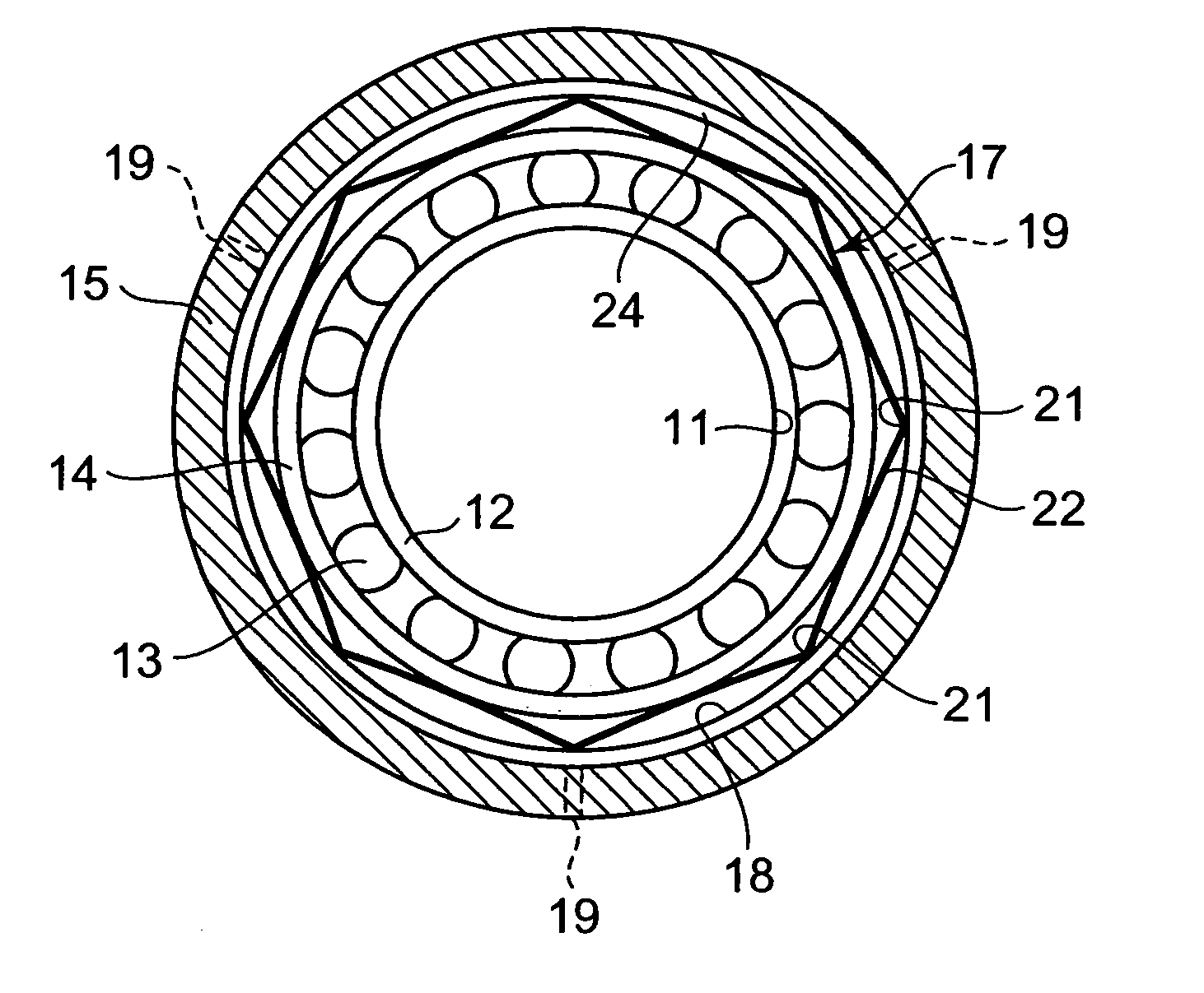
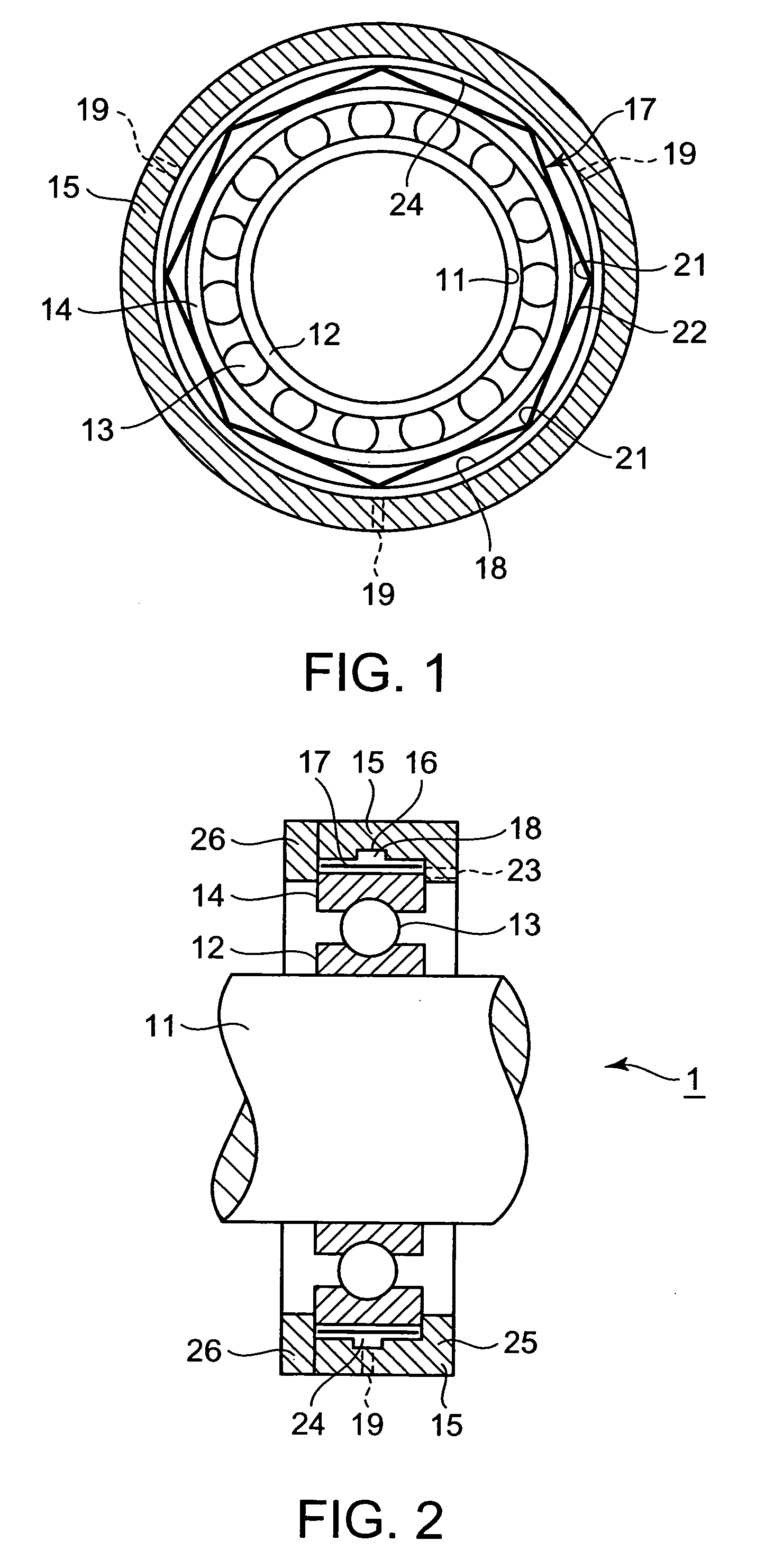
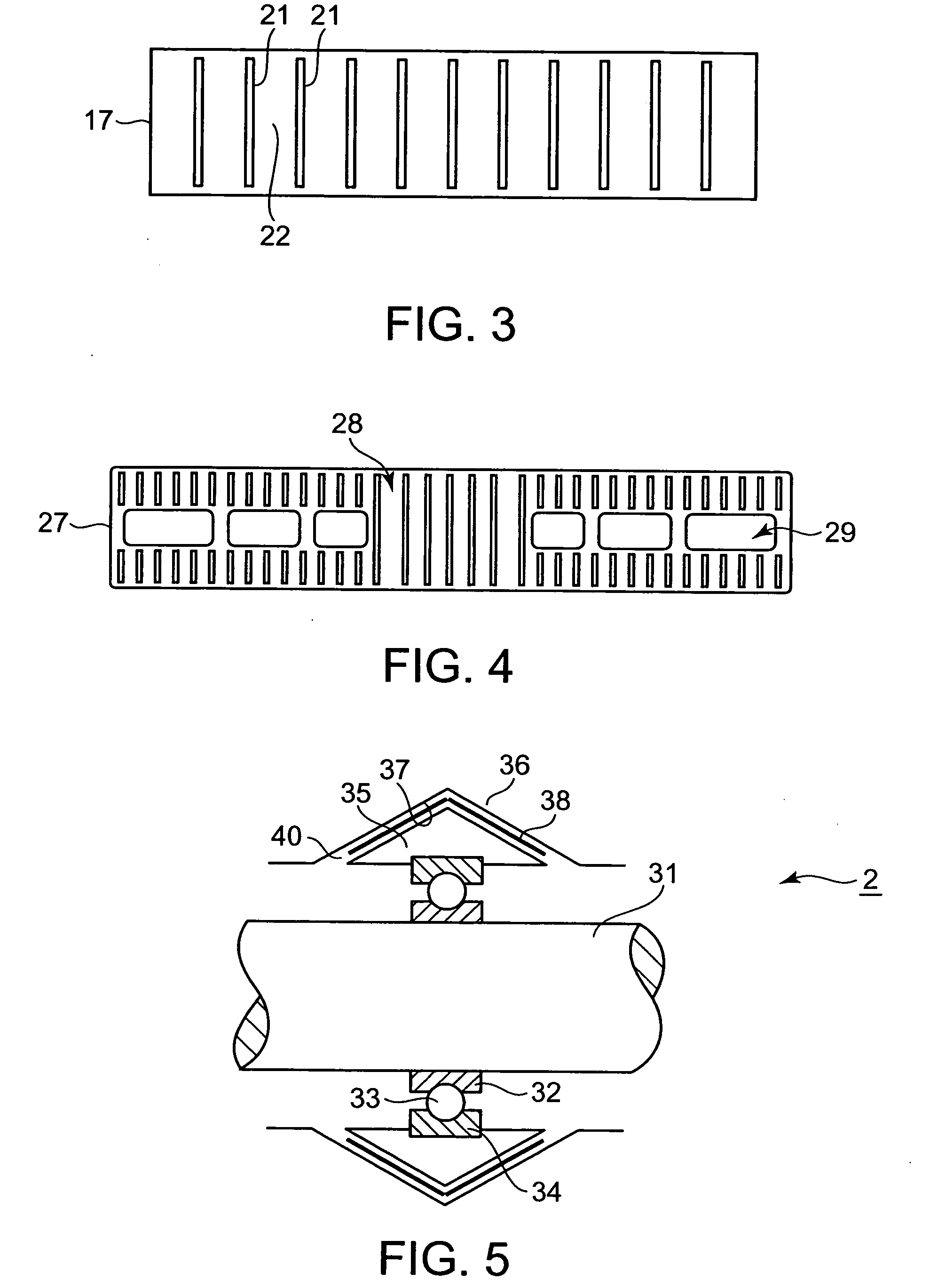
[0041]A bearing vibration damping mechanism 1 in a first embodiment according to the present invention will be described with reference to FIGS. 1 to 4. FIG. 1 is a plan view of the bearing vibration damping mechanism 1, FIG. 2 is a longitudinal sectional view of the bearing vibration damping mechanism 1, FIG. 3 is a plan view of a thin plate spring included in the bearing vibration damping mechanism 1 and FIG. 4 is a plan view of another thin plate spring that can be included in the bearing vibration damping mechanism 1.

[0042]The bearing vibration damping mechanism 1 in the first embodiment is used in combination with a rolling bearing including an inner ring 12, rolling elements 13 and an outer ring 14. The bearing vibration damping mechanism 1 damps the vibration of the rolling bearing. As shown in FIGS. 1 and 2, a rotating shaft 11 is supported in the inner ring 12 and the inner ring 12 is supported by the rolling elements 13, such as balls or rollers, on the outer ring 14.

[0043...

second embodiment

[0061]A bearing vibration damping mechanism in a second embodiment according to the present invention for a rolling bearing includes a bearing housing provided with an annular groove having a triangular cross section instead of the bearing housing provided with the bearing holding bore 16 of the first embodiment. An annular member having a conical surface is attached to the outer ring of a bearing and is fitted in the annular groove. A thin, flat sheet provided with a plurality of slits is inserted into a space defined by the annular member and the bottom surface of the annular groove, a lubricating oil or a lubricating grease is supplied into the space to form a squeeze film damper for damping vibrations by the lubricating oil or grease.

[0062]In the bearing vibration damping mechanism in the second embodiment, the space formed between the annular member and the bottom surface of the annular groove has opposite parts inclined in opposite directions, respectively, to a perpendicular ...


PUM


Abstract

A squeeze film damper for a bearing and a vibration damping mechanism capable of damping the vibration of a rolling bearing are provided. The squeeze film damper is small in construction and can be easily made by mass production. The vibration damping mechanism is capable of damping both radial and axial vibrations. A bearing housing 15 is provided with a bearing holding bore 16 of a diameter greater than the outside diameter of the outer ring 14 of a bearing, and an oil hole 19 through which oil is supplied into the bearing holding bore 16. A vibration damping mechanism 1 is formed by inserting a thin, flat sheet 17 provided with slits into an annular space formed between the inner wall of the bearing holding bore 16 and the outside surface of a bearing held in the bearing holding bore 16 so as to surround the bearing. Parts of the thin, flat sheet extending between the adjacent slits serve as elastic beams. The elastic beams center the bearing and support the centered bearing elastically. The vibration of the bearing is damped by the squeeze film effect of an oil film formed by supplying oil into the annular space.

Description

TECHNICAL FIELD[0001]The present invention relates to a bearing vibration damping mechanism capable of exerting a damping action on a rolling bearing, and more particularly to a supplementary mechanism facilitating the adjustment of the damping characteristic of a squeeze film damper for a bearing.BACKGROUND ART[0002]Rolling bearings are used widely in a variety of machines because rolling bearings, as compared with sliding bearings, cause small friction loss. Effective damping action for damping the vibration of a rolling bearing when rotating speed rises beyond a critical speed can be scarcely expected from the rolling bearing in view of the construction of the rolling bearing. Therefore, a damper is incorporated into a rolling bearing to provide the rolling bearing with a vibration damping ability in order to reduce vibrations of a machine and dynamic load on the rolling bearing and to extend the life of the bearing.[0003]A squeeze film damper is used in combination with the roll...

Claims


Application Information

Patent Timeline
Patent Type & Authority Applications(United States)
IPC IPC(8): F16C27/06F16C27/04F16C19/06F16C33/58F16F1/18F16F15/023F16F15/073
CPCF16F15/0237F16C27/045F16C19/06F16C2300/02F16C27/00F16C27/04
Inventor WADA, HISAOKAIDO, HIDEO
Owner KAWASAKI HEAVY IND LTD
Why Eureka
Try Eureka