
Radio frequency reflect-array single panel for satellite antenna and an assembly of radio frequency reflect-array panels for satellite antenna comprising at least one such panel

a technology of radio frequency reflectors and satellite antennas, which is applied in the direction of antennas, space fed arrays, electrical devices, etc., can solve the problems of high cost to satisfy functional requirements, unstable coefficient of thermal expansion of art, and high cost to meet functional requirements

Active Publication Date: 2020-03-19
THALES SA
View PDF0 Cites 1 Cited by
  • Summary
  • Abstract
  • Description
  • Claims
  • Application Information

AI Technical Summary

Benefits of technology

The invention is a fixing device for a radio frequency tile that helps to minimize deformations in the RF tile caused by thermal loading. This is important for maintaining antenna performance levels. The device prevents deformations in the RF tile by using a spacer layer and flanging effect on the structural panel, which ensures a necessary rigidity and limits the impact on antenna performance. Additionally, the device ensures dimensional stability of the RF tile by limiting deformations to that of the structural panel. This is important because commercially available coefficients of thermal expansion for the materials used in the RF tile are currently limited, requiring a more rigid fixing solution.

Problems solved by technology

Radio frequency reflectors are known for parabolic satellite antennas of large sizes, for example of the order of 6 m diameter, which are technically complicated and therefore of high cost to satisfy the functional requirements demanded by the mission (particularly with respect to the geometrical stability in orbit).
However, the planar panels of the state of the art pose a problem of thermal expansion when they have to operate at radio frequencies, given the thermal gradients that exist along such external appendages.
These materials are indeed efficient in RF mode, but remain unstable with respect to their coefficient of thermal expansion (of the order of 10, or even 12 ppm / ° C.) for temperature variations that are observed in orbit.

Method used


Image

  • Radio frequency reflect-array single panel for satellite antenna and an assembly of radio frequency reflect-array panels for satellite antenna comprising at least one such panel
  • Radio frequency reflect-array single panel for satellite antenna and an assembly of radio frequency reflect-array panels for satellite antenna comprising at least one such panel
  • Radio frequency reflect-array single panel for satellite antenna and an assembly of radio frequency reflect-array panels for satellite antenna comprising at least one such panel

Examples


Embodiment Construction

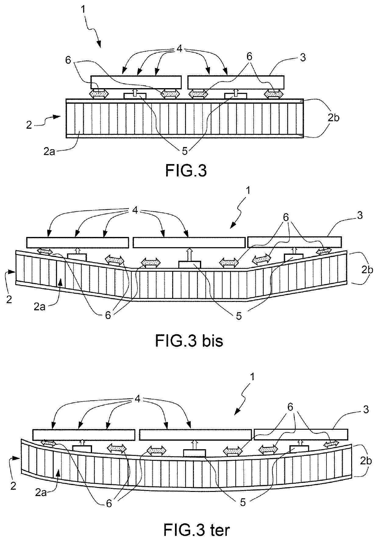
[0078]FIG. 3 represents a radio frequency reflective array panel 1 according to one aspect of the invention, in cross section, comprising:[0079]a structural support 2;[0080]radio frequency tiles 3 supporting polygonal radio frequency cells 4 configured to reflect and phase-shift incident radio frequency signals;[0081]a complete link 5, between the structural support 2 and the radio frequency tile 3; and[0082]at least two runner-type links 6, between the structural support 2 and the radio frequency tile 3, in the plane of the panel 1, of distinct axes and passing through the complete link 5.

[0083]The complete link 5 can be situated at the middle of a tile or at the edge of a tile.

[0084]The structural support 2 comprises a spacer layer 2a coated with two skins 2b of draped orthotropic material, less than 1 mm thick, configured to ensure a quasi-isotropic equivalent Young's modulus lying between 100 and 200 GPa, and a coefficient of thermal expansion less than or equal to 3 ppm / ° C.

[00...


PUM


Abstract

A radio frequency reflect-array panel for satellite antenna, includes a structural support; radio frequency tiles supporting polygonal radio frequency cells configured to reflect and phase-shift incident radio frequency signals; a complete link, between the structural support and the radio frequency tile; and at least two runner-type links, between the structural support and the radio frequency tile, in the plane of the panel, of distinct axes and passing through the complete link.

Description

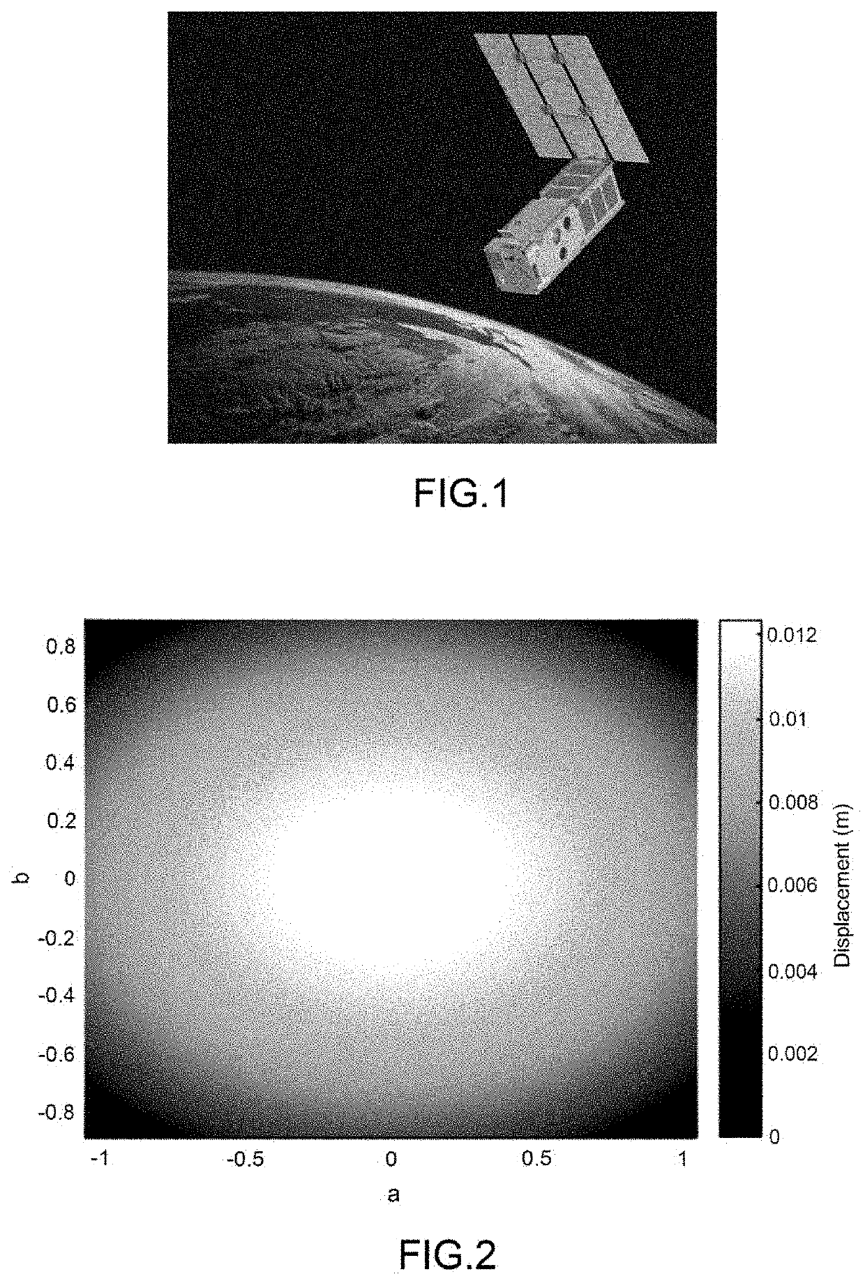
CROSS-REFERENCE TO RELATED APPLICATIONS[0001]This application claims priority to foreign French patent application No. FR 1800957, filed on Sep. 13, 2018, the disclosure of which is incorporated by reference in its entirety.FIELD OF THE INVENTION[0002]The invention relates to a radio frequency reflect-array single panel for satellite antenna and an assembly of radio frequency reflect-array panels for satellite antenna comprising at least one such panel.BACKGROUND[0003]Radio frequency reflectors are known for parabolic satellite antennas of large sizes, for example of the order of 6 m diameter, which are technically complicated and therefore of high cost to satisfy the functional requirements demanded by the mission (particularly with respect to the geometrical stability in orbit).[0004]Reflective array panels are known, such as those embedded on the “cubesat” satellite, called “Integrated Solar Array and Reflectarray Antenna”, of acronym ISARA, as illustrated in FIG. 1.[0005]Also kn...

Claims


Application Information

Patent Timeline
IPC IPC(8): H01Q15/14
CPCH01Q15/14H01Q15/141H04B7/18515H01Q3/46H01Q15/148H01Q21/0018
Inventor DAVID, JEAN-FRANÇOISCHINIARD, RENAUD
Owner THALES SA
Learn More