Internal combustion engine provided with decompressing mechanism

Inactive Publication Date: 2005-02-22
HONDA MOTOR CO LTD
View PDF10 Cites 1 Cited by
  • Summary
  • Abstract
  • Description
  • Claims
  • Application Information

AI Technical Summary

Benefits of technology

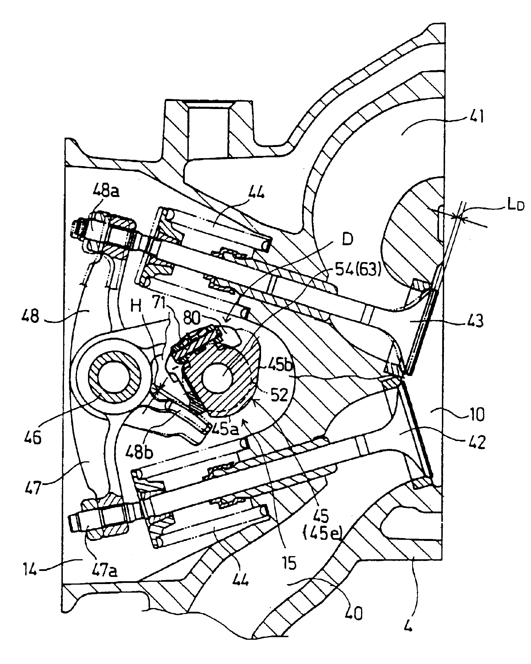
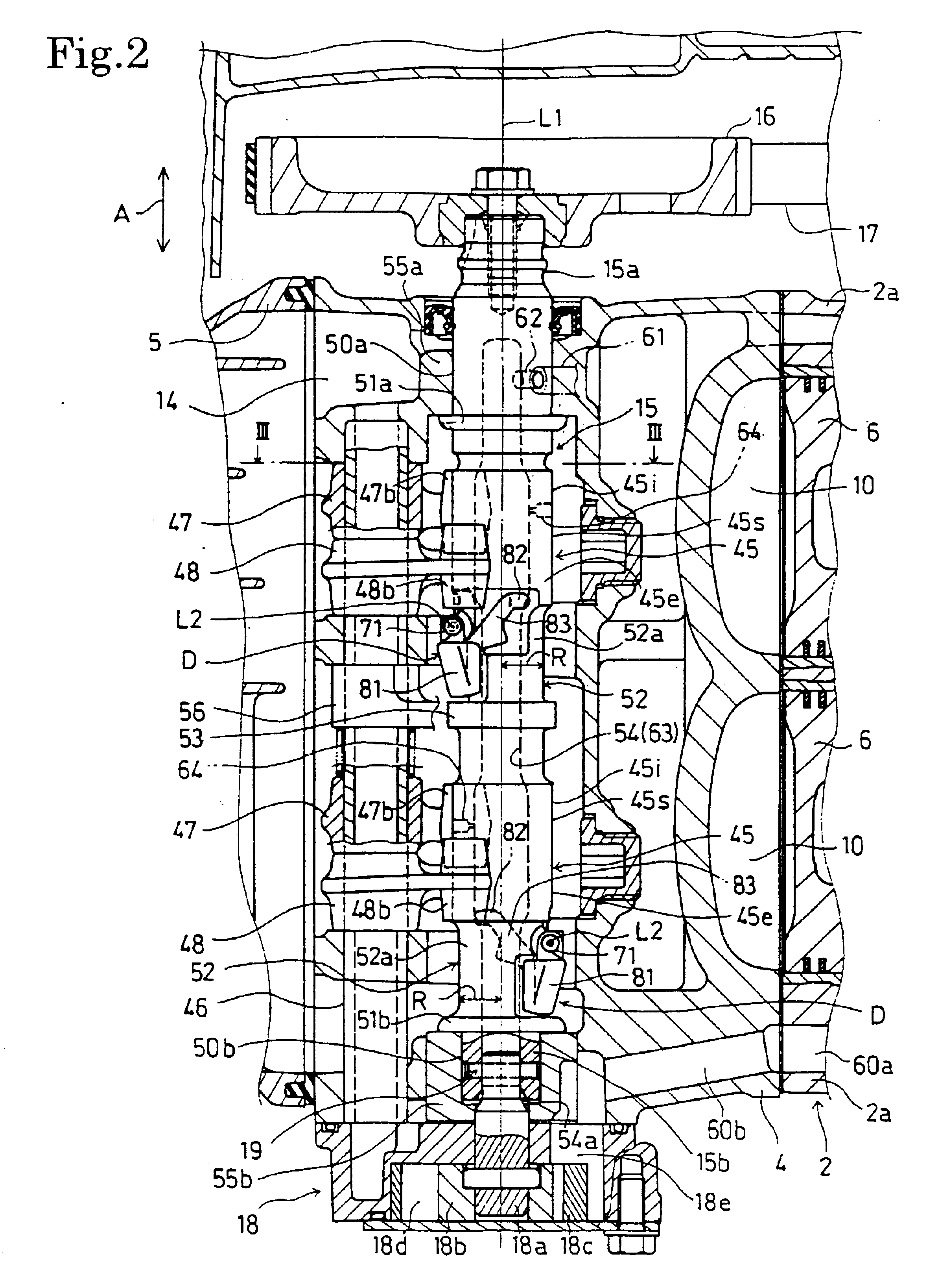
In the decompressing mechanism including the flyweight having the weight body and the projections engaged with the pin, and the arm, the mass ratio of the weight body to the decompressing mechanism is large. The weight body is formed in the width along the axis of swinging motion greater than the thickness of the arm, and in the thickness in the radial direction greater than the thickness of the arm to form the decompressing mechanism of component parts respectively having different thicknesses. Therefore, the flyweight has a necessary rigidity, the mass of the atm can be reduced to the least possible extent, most of the mass of the decompressing mechanism is concentrated on the weight body, and the weight body is disposed in a space radially inside the camshaft such that the weight body overlaps the camshaft as viewed from the direction perpendicular to the reference plane.
The decompressing mechanism thus formed has the following effects. Since the decompressing mechanism includes the flyweight having the weight body and the projections, and the arm, and the weight body has the width and the thickness which are greater than the thickness of the arm, the decompressing mechanism is lightweight and most of the mass of the decompressing mechanism can be concentrated on the weight body. The weight body overlapping the camshaft as viewed from the direction perpendicular to the reference plane suppresses the enlargement of the decompressing mechanism, and therefore the fully expanded decompressing mechanism is able to revolve around the camshaft in a small cylindrical space around the camshaft or the expansion of the cylindrical space can be suppressed.
Preferably, the camshaft has a holding part including projections provided with first holes, respectively, the projections of the flyweight are provided with second holes, respectively, the pin is inserted in the first holes so as to be turnable therein and is inserted in the second holes to support the flyweight for tog, and an end pant projecting outside from one of the first or the second holes is pressed to form an expanded part for preventing the pin from coming off the first and the second holes.
Thus, the following effect is produced. The pin can be prevented from coming off the first and the second holes simply by pressing the end part thereof.
The arm may be extended from the weight body. Since the projections through which the pin is inserted, and the arm connecting the flyweight and the decompression cam can be thus extended in different directions, respectively, from the weight body, the thicknesses and the shapes of the projections and the arm can be individually determined, and the optimum designing of the positional relation or the flyweight and the arm with the camshaft, the projections, the weight body and the arm is possible.
Although the decompressing mechanism is formed by integrally combining the component parts respectively having different thicknesses, the flyweight, the decompression cam and the arm can be formed in high dimensional accuracy. Since the flyweight, the decompression cam and the arm respectively having different thicknesses are formed integrally in high dimensional accuracy, the decompressing mechanism has an operating characteristic in a narrow range around a reference operating characteristic, and the decompressing mechanism capable of exhibiting a stable operating characteristic can be easily manufactured.

Problems solved by technology

Therefore, it is difficult to concentrate a large part of the mass of the lever on the weight to generate a high centrifugal force necessary for stopping a decompressing operation at a set engine speed without increasing the weight of the lever.
Therefore, the mass ratio of the weight to the lever of the decompressing means of the prior art B is greater than that of the weight to the lever of the decompressing means of the prior art A. However, since the thickness of the weight is equal to that of the arm, i.e., the thickness of a plate forming the lever, it is difficult to concentrate mass on the weight simultaneously with the reduction of the size of the decompressing means.
Thus the concentration of mass on the weight increases working steps, and requires difficult work because the lever has a complicated shape.

Method used


Image

  • Internal combustion engine provided with decompressing mechanism
  • Internal combustion engine provided with decompressing mechanism
  • Internal combustion engine provided with decompressing mechanism

Examples


Embodiment Construction

An internal combustion engine provided with decompressing mechanisms in a preferred embodiment of the present invention will be described with reference to the accompanying drawings.

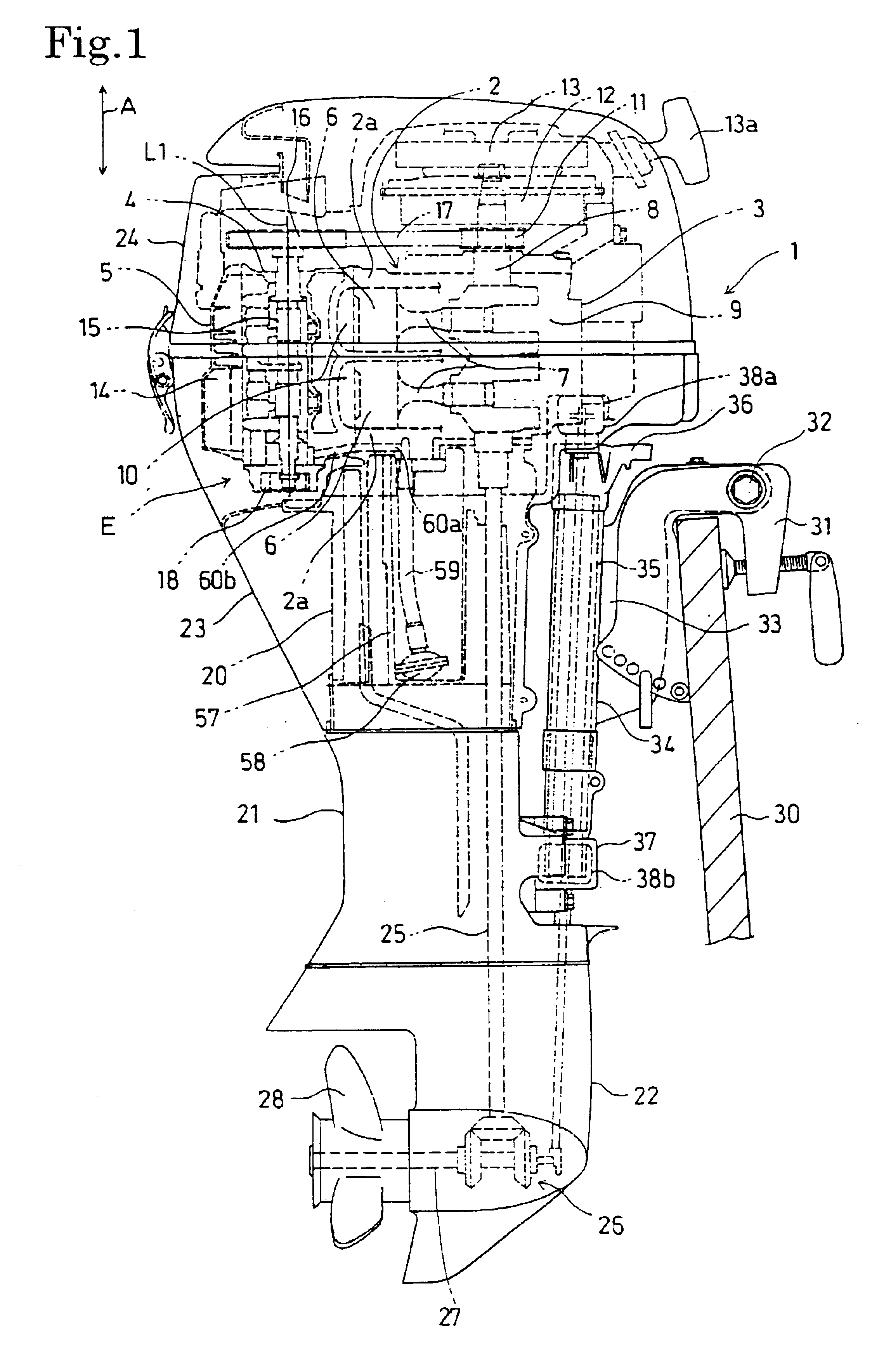
Referring to FIG. 1, an internal combustion engine E provided with decompressing mechanisms D according to the present invention is a water-cooled, inline, two-cylinder, four-stroke-cycle, vertical internal combustion engine installed in an outboard motor with the axis of rotation of its crankshaft 8 vertically extended. The internal combustion engine E comprises a cylinder block 2 provided with two cylinder bores 2a in a vertical, parallel arrangement with their axes longitudinally horizontally extended, a crankcase 3 joined to the front end of the cylinder block 2; a cylinder head 4 joined to the rear end of the cylinder block 2; and a cylinder head cover joined to the rear end of the cylinder head 4. The cylinder block 2, the crankcase 3, the cylinder head 4 and the cylinder head cover 5 constitute an...


PUM


Abstract

A decompressing mechanism included in an internal combustion engine has a flyweight supported for swinging motion by a pin on the camshaft of the internal combustion engine, a decompression cam and an arm connecting the flyweight and the decompression cam and having the shape of a plate. The flyweight has a weight body and projections projecting from the weight body and engaged with the pin. The weight body is a block of a width along the axis of swinging motion and a thickness, along a radial direction, which are greater than the thickness, along the axis, of swinging motion of the arm. The weight body overlaps the camshaft as viewed from a direction perpendicular to a reference plane. The decompressing mechanism is small, lightweight and is capable of concentrating most of its mass on the flyweight.

Description

BACKGROUND OF THE INVENTION1. Field of the InventionThe present invention relates to an internal combustion engine provided with a centrifugal decompressing means for reducing compression pressure to facilitate starting the internal combustion engine by opening a valve included in the internal combustion engine during the compression stroke in starting the internal combustion engine.2. Description of the Related ArtInternal combustion engines provided with a centrifugal decompressing means including a flyweight are disclosed in JP2000-227064A and JP11-294130A. The decompressing means of those known techniques, which will be referred to as “prior art A”, includes a lever provided with a weight and a decompression cam, and having the shape of a flat plate of a substantially uniform thickness. The lever is supported for turning at two parts thereof diametrically facing a camshaft by a pin on the camshaft. The decompression cam is connected to the weight by two arms extending from the t...

Claims


Application Information

Patent Timeline
IPC IPC(8): F02B75/20F01L13/08F02B75/00F02B61/04F02B61/00F02B75/18F02B75/02
CPCF01L13/085F02B61/045F02B75/20F01L1/024F01L2001/0535F02B2075/1808F02B2075/027F01L2101/00F01L2301/00
Inventor YOSHIDA, HIROYUKIIKUMA, TOMONORITANAKA, MITSUHARU
Owner HONDA MOTOR CO LTD
Why Eureka
Try Eureka