
Multiplexer

Pending Publication Date: 2021-09-23
MURATA MFG CO LTD
View PDF0 Cites 0 Cited by
  • Summary
  • Abstract
  • Description
  • Claims
  • Application Information

AI Technical Summary

Benefits of technology

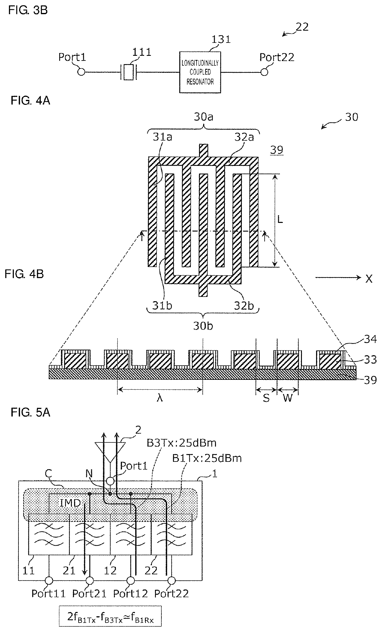
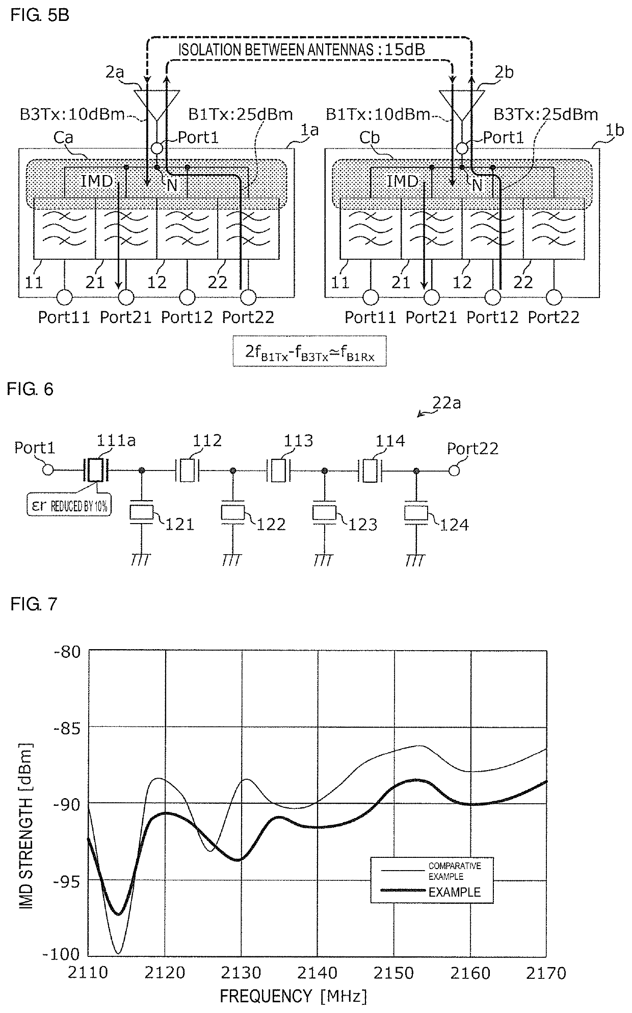
The present invention provides multiplexers that effectively reduce IMD without optimally designing impedance. This is achieved by setting the relative permittivity of the resonator closest to the common terminal to be low, which increases the area of the resonator and reduces power consumption per unit area. This results in a reduction of IMD. Although the size of the resonator is increased, the effect of reducing IMD is maximized.

Problems solved by technology

Such IMD causes an adverse influence, such as degradation of reception sensitivity of a filter.
However, in the case of a multiplexer, due to the relationship between a resonator near an ANT end, which is most affected by IMD, and a filter to which the resonator is commonly connected, there are constraints described below when dividing the resonator so that the area of the resonator increases.
Thus, increasing the area of the resonator near the ANT end, which is intended by Japanese Unexamined Patent Application Publication No. 2007-074698, may not be possible, and the effect of reducing IMD may not be sufficiently achieved.

Method used


Image

  • Multiplexer
  • Multiplexer
  • Multiplexer

Examples


first preferred embodiment

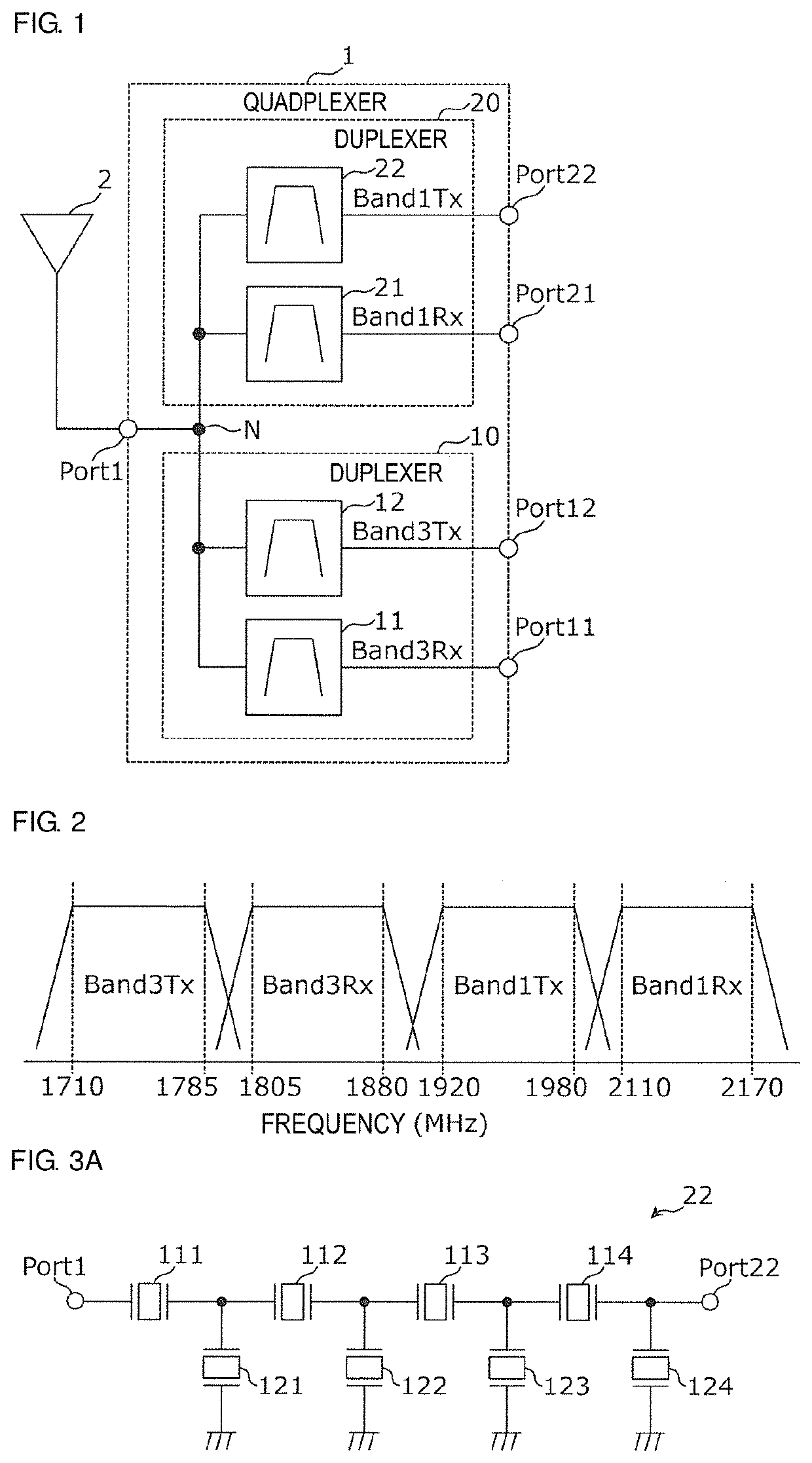
[0032]A multiplexer according to a first preferred embodiment of the present invention will be described using a quadplexer as an example.

[0033]FIG. 1 is a block diagram illustrating an example of the functional configuration of a basic quadplexer according to the present preferred embodiment. In FIG. 1, an antenna element 2 that is connected to a common terminal Port1 of a quadplexer 1 is also illustrated.

[0034]The quadplexer 1 supports, for example, LTE® (Long Term Evolution), and transmits high frequency signals in Bands, which will be described later, defined by 3GPP® (Third Generation Partnership Project).

[0035]As illustrated in FIG. 1, the quadplexer 1 includes the common terminal Port1, four individual terminals Port11, Port12, Port21, and Port22, and four filters 11, 12, 21, and 22.

[0036]The common terminal Port1 is provided in common for the four filters 11, 12, 21, and 22 and is connected to the filters 11, 12, 21, and 22 inside the quadplexer 1. Furthermore, the common te...

second preferred embodiment

[0103]A multiplexer to which a filter according to a second preferred embodiment of the present invention is applied will be described referring to a multiplexer including a band pass filter and a notch filter as an example.

[0104]FIG. 11 is a block diagram illustrating an example of the configuration of a multiplexer according to the second preferred embodiment of the present invention. As illustrated in FIG. 11, a multiplexer 6 includes a common terminal Port6, two individual terminals Port61 and Port62, and two filters 61 and 62.

[0105]The common terminal Port6 is provided in common for the two filters 61 and 62 and is connected to the filters 61 and 62 inside the multiplexer 6. Furthermore, the common terminal Port6 is connected to an antenna element 2 outside the multiplexer 6. That is, the common terminal Port6 also defines and functions as an antenna terminal of the multiplexer 6.

[0106]The filter 61 is a band pass filter that is on a path connecting the common terminal Port6 to...


PUM


Abstract

A multiplexer includes a first filter on a first path, a second filter on a second path, and a third filter on a third path. A frequency of intermodulation distortion generated by a transmission signal within a pass band of the first filter and a transmission signal within a pass band of the second filter is within a pass band of the third filter. The first filter includes one or more series resonators on the first path and one or more parallel resonators on one or more paths connecting one or more nodes on the first path to a ground. A relative permittivity of a resonator of the one or more series resonators and the one or more parallel resonators that is closest to a common terminal is lowest among relative permittivities of the resonators.

Description

CROSS REFERENCE TO RELATED APPLICATIONS[0001]This application claims the benefit of priority to Japanese Patent Application No. 2018-238056 filed on Dec. 20, 2018 and is a Continuation Application of PCT Application No. PCT / JP2019 / 044352 filed on Nov. 12, 2019. The entire contents of each application are hereby incorporated herein by reference.BACKGROUND OF THE INVENTION1. Field of the Invention[0002]The present invention relates to a multiplexer.2. Description of the Related Art[0003]In recent years, multiplexers including an acoustic wave filter have been widely used. In acoustic wave filters, IMD (Intermodulation Distortion) is likely to occur due to nonlinearity of the acoustic wave filters.[0004]When two or more signals of different frequencies are input to an acoustic wave filter as a nonlinear device, a composite signal of a frequency based on a combination of sums or differences of the frequencies is generated due to IMD. In the case where the frequency of the composite sign...

Claims


Application Information

Patent Timeline
IPC IPC(8): H04B1/00H04B1/04H03H9/64H03H3/02
CPCH04B1/0078H04B1/0483H03H2003/027H03H9/6483H03H3/02H04B1/0057H04B1/525H03H9/706H03H9/725H03H9/02015H03H9/72H03H9/14538H03H7/0161
Inventor OKUDA, TETSURO
Owner MURATA MFG CO LTD
Learn More