Synchronous Machine with Magnetic Rotating Field Reduction and Flux Concentration

Active Publication Date: 2019-09-12
EMF 97 ELEKTRO MASCH VERTRIEB MAGNETTECHN & FORSCHUNGS
View PDF0 Cites 0 Cited by
  • Summary
  • Abstract
  • Description
  • Claims
  • Application Information

AI Technical Summary

Benefits of technology

[0036]Disc armatures can be made particularly compact and thus have an advantageous design. By the arrangement of permanent magnets, which extend in the radial direction on the rotor disc, high densities of magnetically active material can be achieved on the disc armature. By the additionally provided permanent magnets, analogous to the previous embodiments, an additional magnetic flux is generated in the flux guide regions, which is directed opposite to the magnetisation direction of the permanent magnets. Thus, the flux guide plates enclosing the at least one disc armature and the at least one stator very effectively introduce the magnetic flux generated by the additional permanent magnet into the radial planes of the disc armature and lead to a significant increase in the flux density in the flux guide regions of the disc armature, up to the saturation limit of the material used. As a result, a significant increase in torque is achieved. In that the axis of rotation and a housing cover of the synchronous machine, said housing cover extending in the axial direction, are made of non-ferromagnetic material, it is achieved that, with respect to the flux guide in the synchronous machine having disc armatures, no flux feedback occurs via the housing or via the axis of rotation and almost the entire magnetic flux of the additional permanent magnet penetrates the radial surfaces of the disc armature/s. In order to utilise the magnetic field of

Problems solved by technology

The provision of torques was previously limited with a constant overall s

Method used


Image

  • Synchronous Machine with Magnetic Rotating Field Reduction and Flux Concentration
  • Synchronous Machine with Magnetic Rotating Field Reduction and Flux Concentration
  • Synchronous Machine with Magnetic Rotating Field Reduction and Flux Concentration

Examples


Embodiment Construction

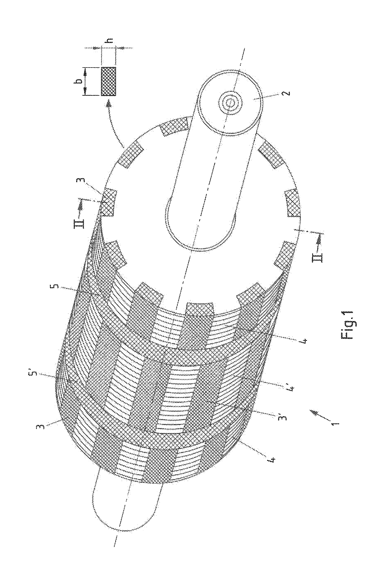
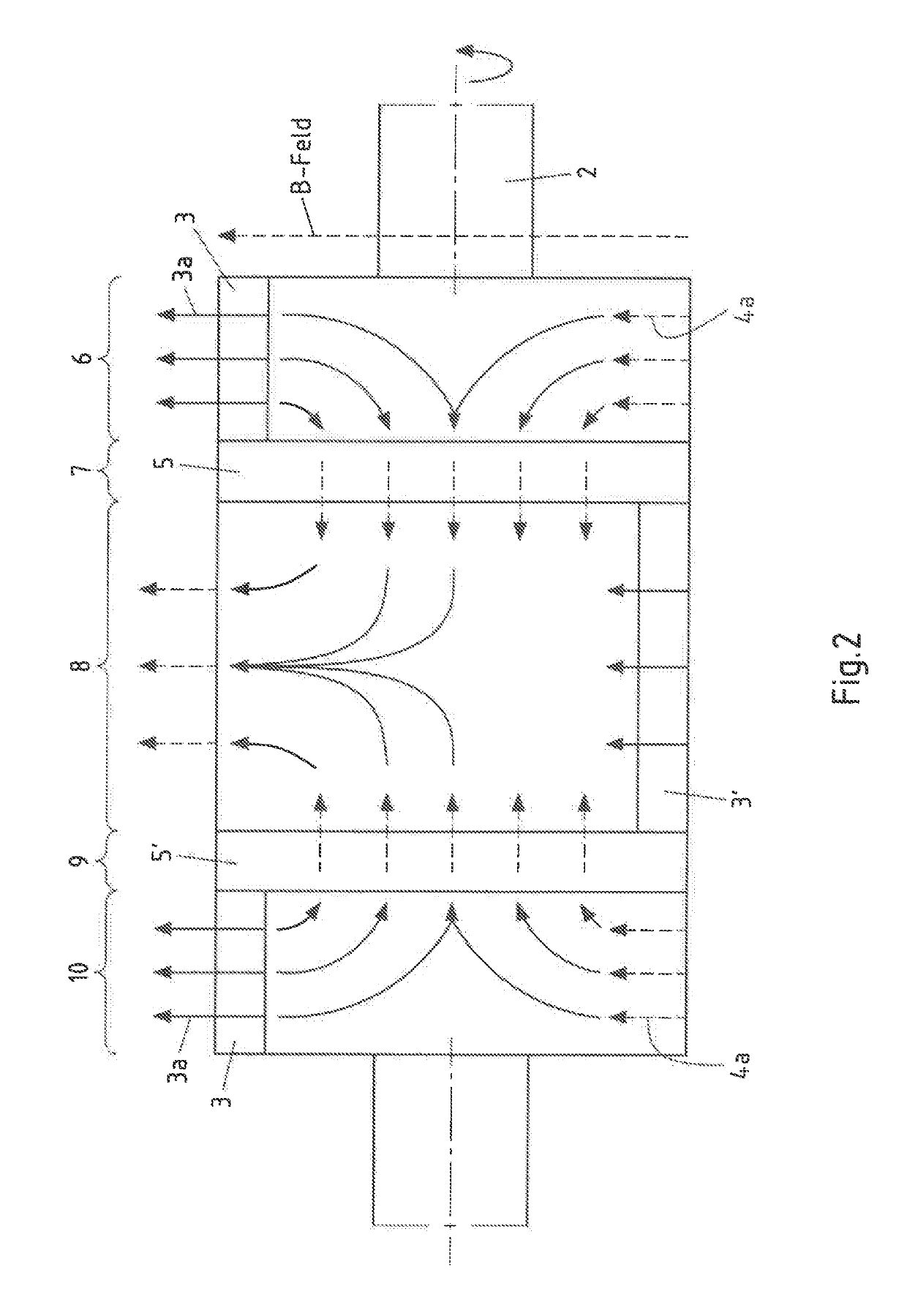
[0048]In FIG. 1, a rotor 1 is shown in the form of a cylindrical armature of a first embodiment of the synchronous machine according to the invention. The rotor 1 is arranged on an axis of rotation 2 and has regions with permanent magnets 3, 3′, which are arranged facing the at least one stator, not shown in FIG. 1, and distributed in angular ranges in the circumferential direction on the rotor. In addition, flux guide regions 4, 4′ are provided on the rotor 1 between the permanent magnets 3, 3′, which serve to guide the magnetic flux from or into the rotor 1. The flux guide regions 4, 4′ are made of a ferromagnetic, preferably soft-magnetic material. Preferably, the flux guide regions are formed as laminated teeth. In this embodiment, the flux guide regions are laminated perpendicular to the axis of rotation. The stator, not shown in FIG. 1, has n grooves, in which the polyphase, preferably three-phase, winding is wound. With the polyphase winding, which has a number of poles 2p4, ...


PUM


Abstract

A synchronous machine with flux concentration. The synchronous machine enables improved torquing characteristics with a simple structure in that at least one additional permanent magnet is provided in the rotor and/or stator, whose generated magnetic flux is at least partially returned via the flux guide regions of the rotor, wherein the magnetic flux of the additional permanent magnet in the flux guide regions of the rotor has a direction opposite to the magnetisation direction of the permanent magnets of the rotor.

Description

CROSS-REFERENCE TO RELATED PATENT APPLICATIONS[0001]This patent application is a continuation of PCT / EP2017 / 079904, filed Nov. 21, 2017, which claims priority to German Application No. 10 2016 122 794.3, filed Nov. 25, 2016, the entire teachings and disclosure of which are incorporated herein by reference thereto.FIELD[0002]The invention relates to a synchronous machine with flux concentration[0003]having at least one stator with a polyphase, preferably three-phase, winding with a number of poles 2p≥4, wherein the number of poles is twice the number of pole pairs p and the winding is arranged in n grooves in the stator and is designed to generate a magnetic rotating field,[0004]having flux guide regions provided between the grooves of the at least one stator for guiding the magnetic rotating field, which comprise a ferromagnetic, preferably soft-magnetic, material,[0005]having at least one rotor arranged on an axis of rotation, which is, relative to at least one stator, rotatably ar...

Claims


Application Information

Patent Timeline
IPC IPC(8): H02K1/27H02K21/24H02K16/00
CPCH02K1/2766H02K16/00H02K21/24H02K1/2713H02K1/278H02K21/14
Inventor LINDNER, JÜRGENPROKOPP, MICHAELHAMES, THOMASKAYAKIRAN, HASAN BASRI
Owner EMF 97 ELEKTRO MASCH VERTRIEB MAGNETTECHN & FORSCHUNGS
Why Eureka
Try Eureka