Catheter system for connecting adjacent blood vessels

Active Publication Date: 2008-05-20
PQ BYPASS
View PDF219 Cites 108 Cited by
  • Summary
  • Abstract
  • Description
  • Claims
  • Application Information

AI Technical Summary

Problems solved by technology

A difficulty here is in co-locating the openings in the two blood vessels and holding the vessel walls in place to ensure that a channel will be created between the vessels so that blood will flow from one vessel to the other.

Method used


Image

  • Catheter system for connecting adjacent blood vessels
  • Catheter system for connecting adjacent blood vessels
  • Catheter system for connecting adjacent blood vessels

Examples


Embodiment Construction

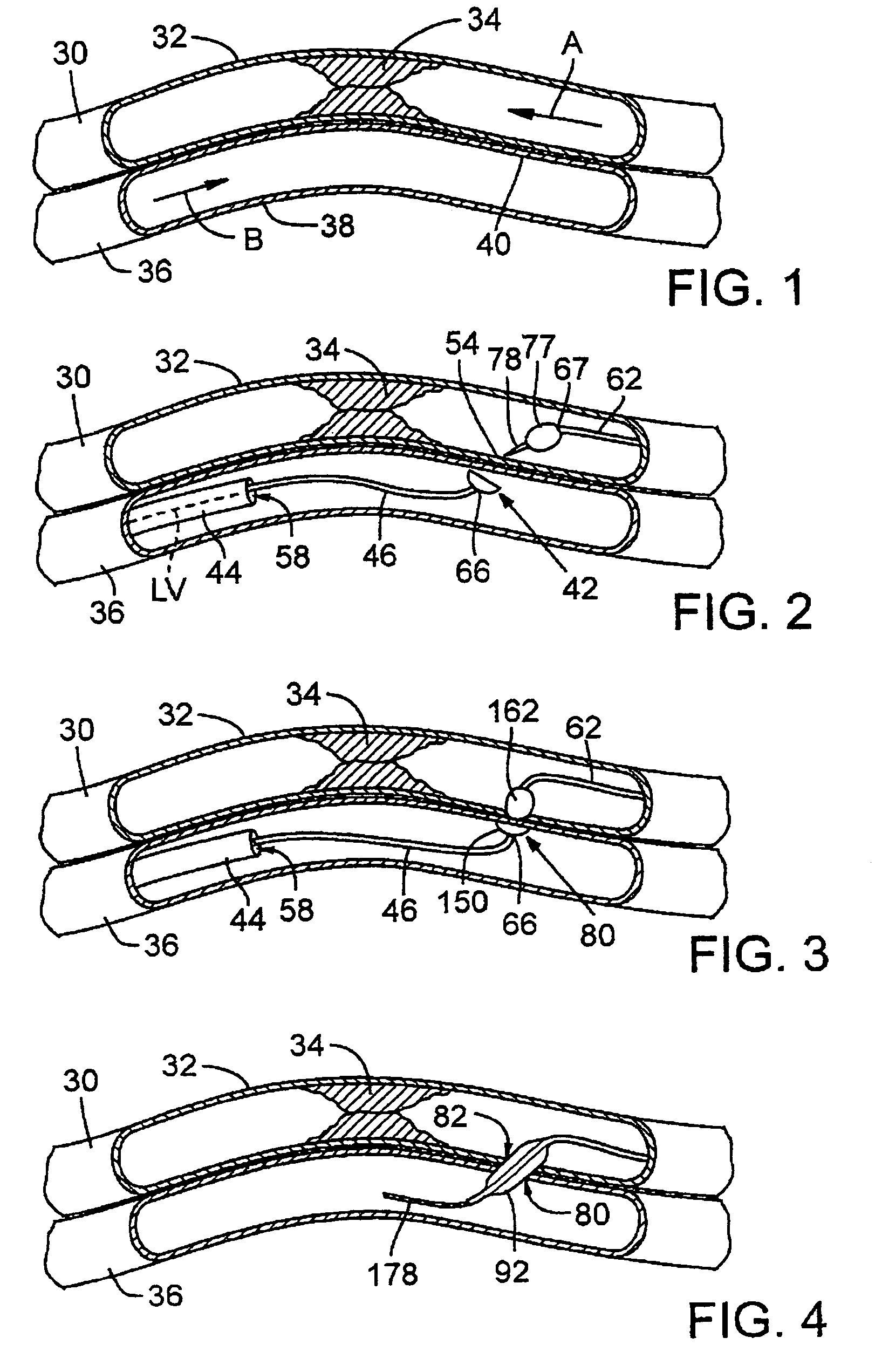
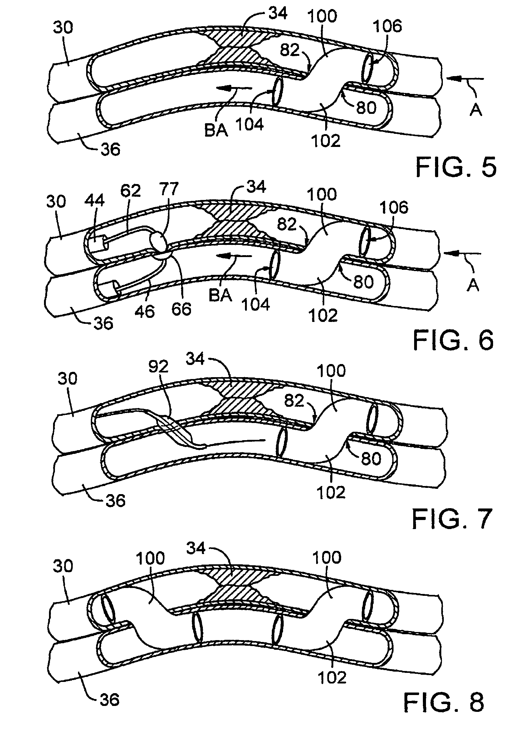
[0017]As shown in FIG. 1, an artery 30, formed by an artery wall 32, has a blood flow, indicated by arrow A, that is partially or totally blocked by an obstruction or occlusion 34, typically formed by plaque. A vein 36 roughly similar in dimension to artery 30 lies alongside and generally parallel to artery 30. Vein 36, formed by a vein wall 38, includes, in the area proximal to occlusion 34, a portion 40 in close proximity to artery 30 that the physician has selected as a venous site for creating a fistula between artery 30 and vein 36. The normal blood flow through vein 36 would be in the direction indicated by arrow B.

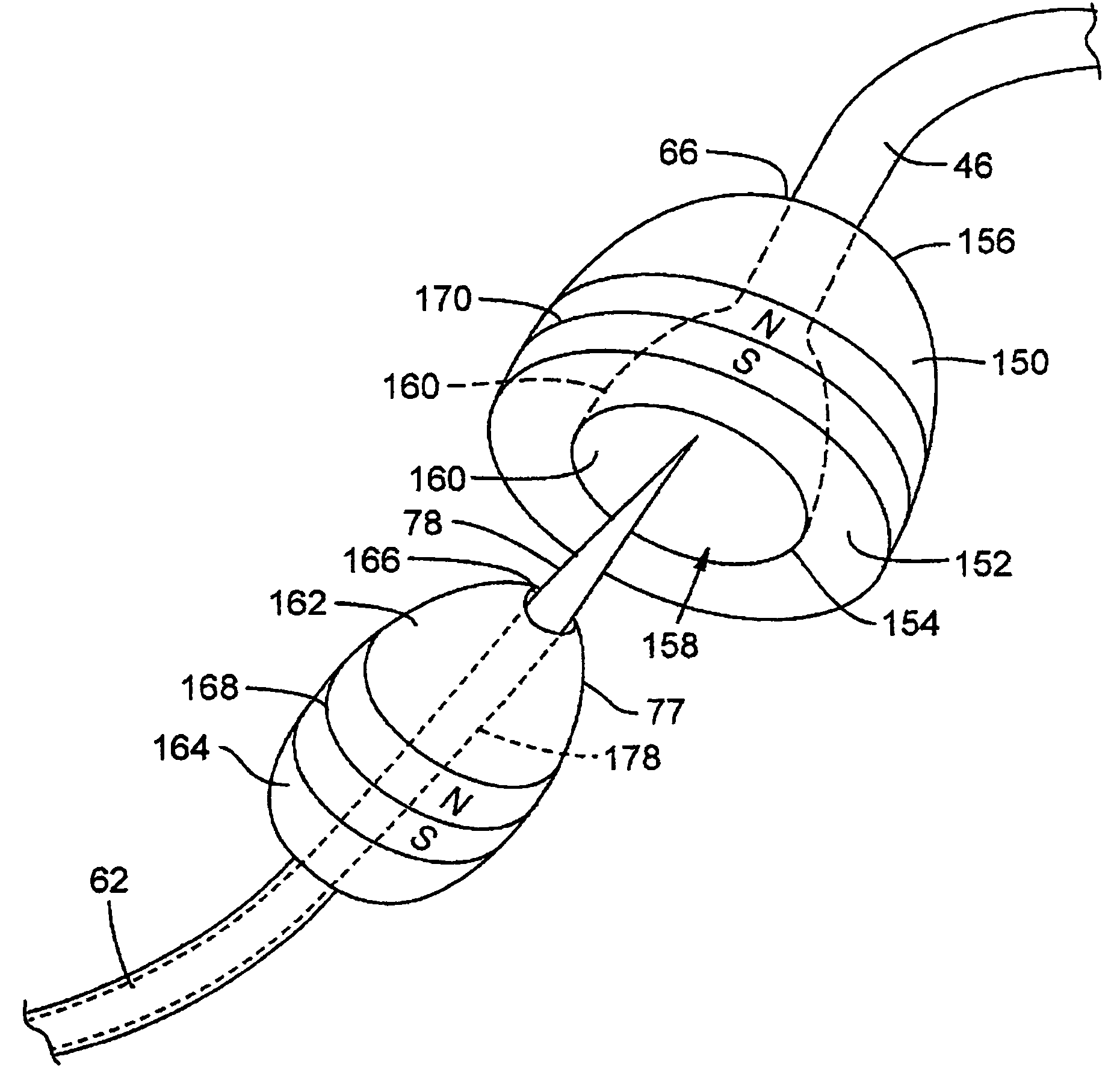
[0018]An embodiment of the invented system, indicated generally at 42 in FIG. 2, is a catheter apparatus that includes a first catheter 62 and a second catheter 44. In FIG. 2, the first catheter is in the artery and the second catheter is in the vein, but this can be reversed. Similarly, the first catheter in the artery is shown upstream from occlusion 34, but this ...


PUM


Abstract

A catheter system is provided for creating a fistula between blood vessels, using a first catheter with a piercing tool adjacent its distal end, and a second catheter with a receptor adjacent its distal end. The receptor includes an opening and a channel providing a guide surface for receiving the piercing tool. The receptor and piercing tool include one or more magnets to draw the piercing tool into the channel of the receptor. The piercing tool and the receptor are provided with a complementary configuration, such as a mating conical shapes. A third catheter may be provided with a double balloon for use in sealing off the fistula site. The piercing tool may be provided on a metal guidewire that includes a lumen with a distal opening. The piercing tool may include a base and a needle coupled to the base at a nominal angle of at least about 20-degrees. The piercing tool may be selectively moved between an extended position wherein the needle is positioned outside the guidewire at the nominal angle and a retracted position wherein the needle is positioned substantially within the guidewire.

Description

BACKGROUND[0001]This invention relates generally to a catheter system for connecting adjacent blood vessels, e.g., an artery and an adjacent vein to adapt the vein for arterial blood flow. More particularly the invention concerns a system of two catheters with mating, magnetic tips for creating openings in the artery wall and vein wall to form a fistula connecting the blood vessels.[0002]A catheter apparatus and method for arterializing a section of a vein to bypass a clogged artery are shown in U.S. Pat. No. 6,464,665, which is hereby incorporated by reference. The method is used to bypass a stenosis in the artery that obstructs blood flow in a portion of the artery. If the obstructed portion of the artery can be bypassed, blood flow will be restored downstream from the stenosis. A vein running alongside the artery in the obstructed portion of the artery can be used for the bypass.[0003]The catheter apparatus includes one catheter for inserting into the artery and another catheter ...

Claims


Application Information

Patent Timeline
Patent Type & Authority Patents(United States)
IPC IPC(8): A61B17/34A61B17/08
CPCA61B17/11A61B17/3478A61B2017/00252A61B2017/00876A61B2017/1107A61B2017/1139
Inventor HEUSER, RICHARD R.
Owner PQ BYPASS
Why Eureka
Try Eureka