
Alarm generation method and apparatus

a technology of alarm generation and apparatus, applied in the direction of electric signalling details, instruments, using reradiation, etc., can solve the problems of not being able to detect a dangerous situation in which the pedestrian or the bicycle moves out, adverse effect on other electronic devices, etc., to reduce the needless consumption of electric energy and the adverse effect of unnecessary radio waves on other electronic devices

Active Publication Date: 2008-05-20
ALPINE ELECTRONICS INC
View PDF4 Cites 20 Cited by
  • Summary
  • Abstract
  • Description
  • Claims
  • Application Information

AI Technical Summary

Benefits of technology

Reduces energy consumption and unnecessary radio wave emissions while effectively alerting drivers to potential hazards, such as pedestrians or bicycles moving into the roadway, thereby enhancing safety.

Problems solved by technology

Unfortunately, the foregoing known technology has a problem, for example, that the on-vehicle equipment must continuously emit a searching radio wave to the mobile device carried by the pedestrian or the cyclist, resulting in a needless consumption of electric energy and also, an adverse effect on other electronic devices due to emission of an unnecessary radio wave.
Also, while placing importance on detecting a pedestrian, a bicycle, or the like as accurately as possible, the known technology is incapable of sensing a dangerous situation in which the pedestrian or the bicycle moves out into the roadway in order to avoid an obstacle on a sidewalk and informing a driver of the situation.
In other words, when a utility pole or the like is installed on a narrow sidewalk, two or more pedestrians have difficulty in proceeding along the narrow sidewalk side by side, thereby causing the pedestrian or the bicycle to likely move out into the roadway.

Method used


Image

  • Alarm generation method and apparatus
  • Alarm generation method and apparatus
  • Alarm generation method and apparatus

Examples


first embodiment

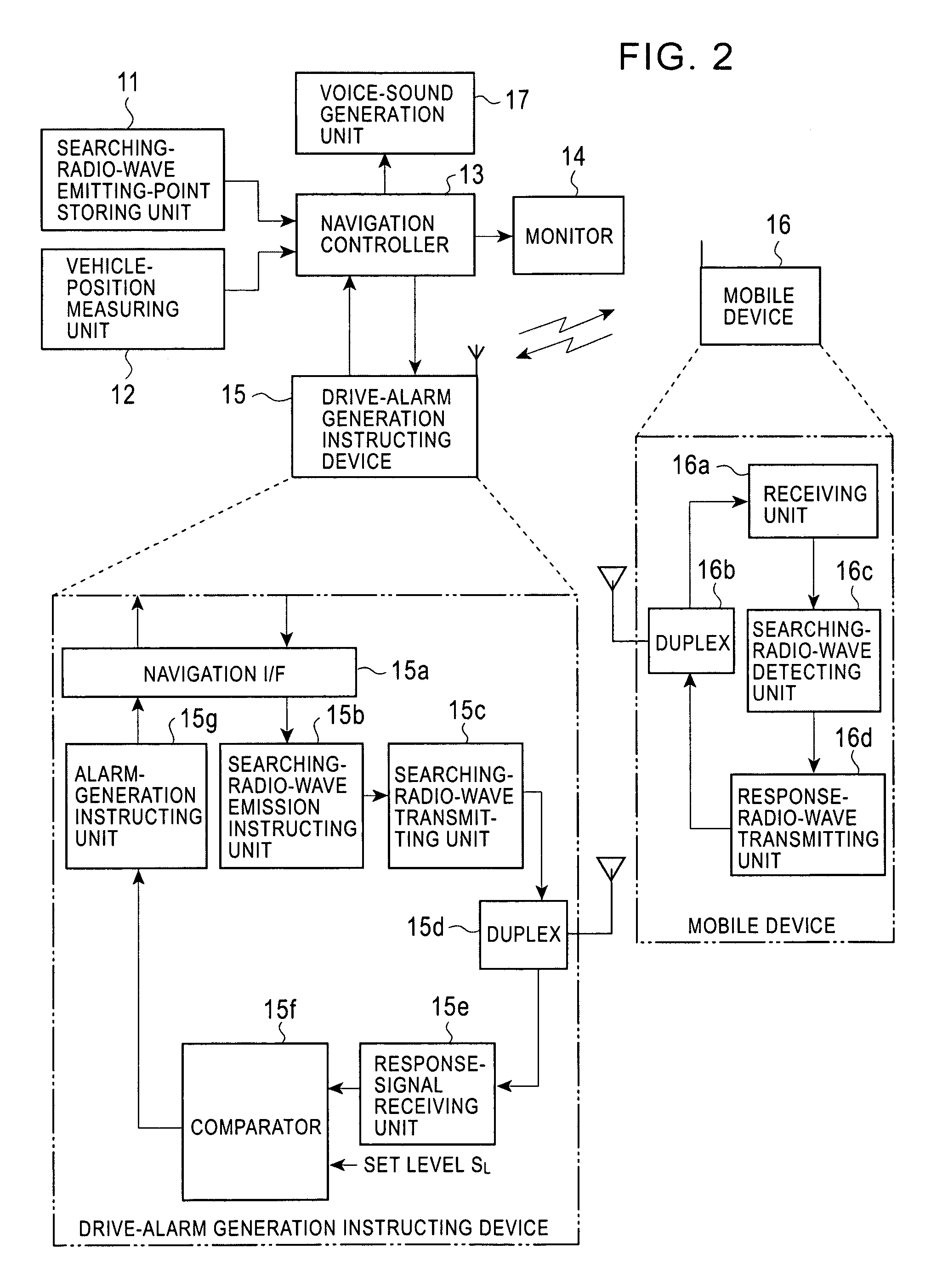
[0030]FIG. 2 is a block diagram of the structure of an alarm generation apparatus according to a first embodiment of the present invention, and FIG. 3 is a flowchart of an operation of the alarm generation apparatus for generating an alarm.

[0031]The alarm generation apparatus generally includes a searching-radio-wave emitting-point storing unit 11, a vehicle-position measuring unit 12, a navigation controller 13, a monitor 14, a drive-alarm generation instructing device 15, a mobile device 16, and a voice-sound generation unit 17.

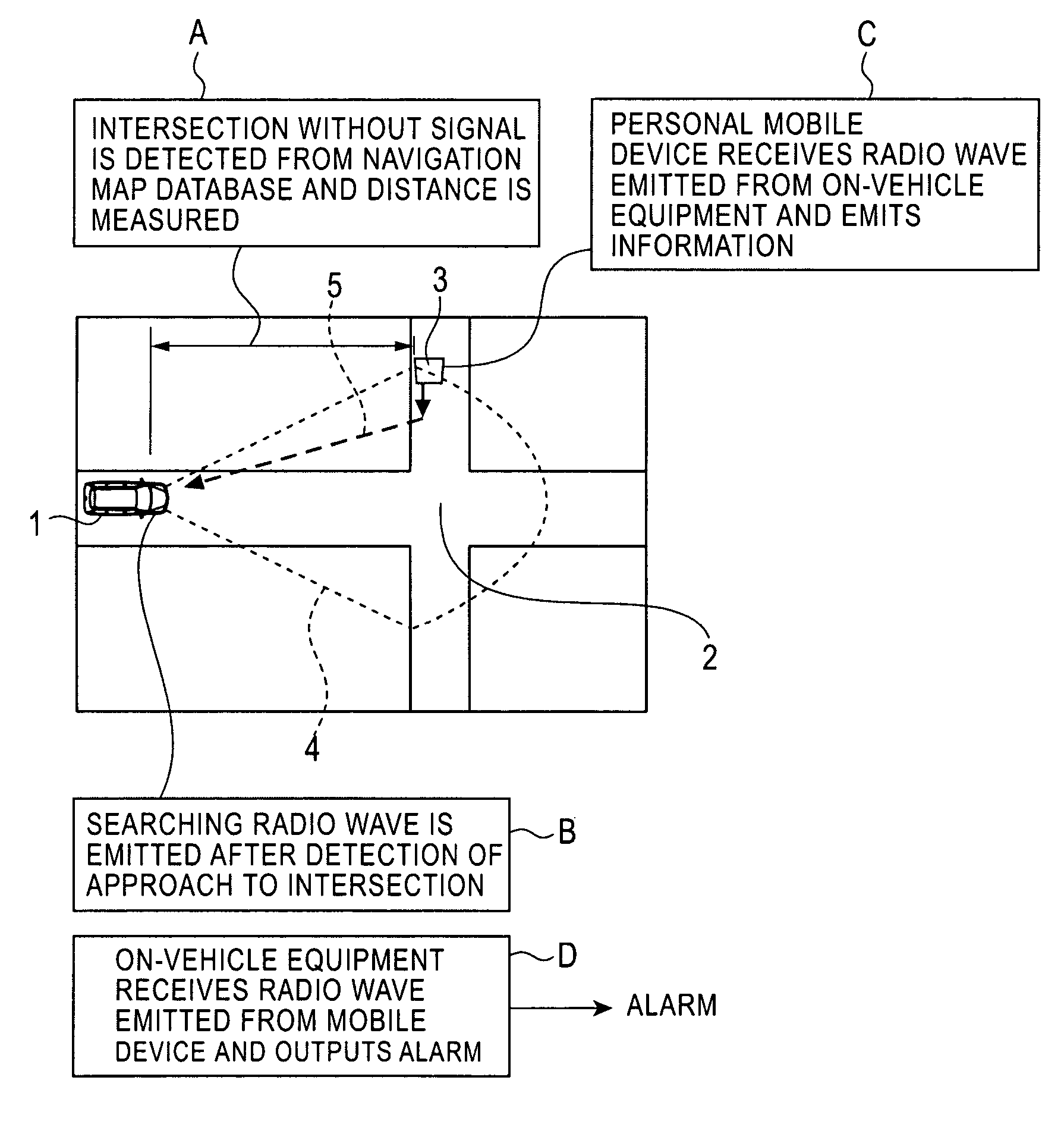
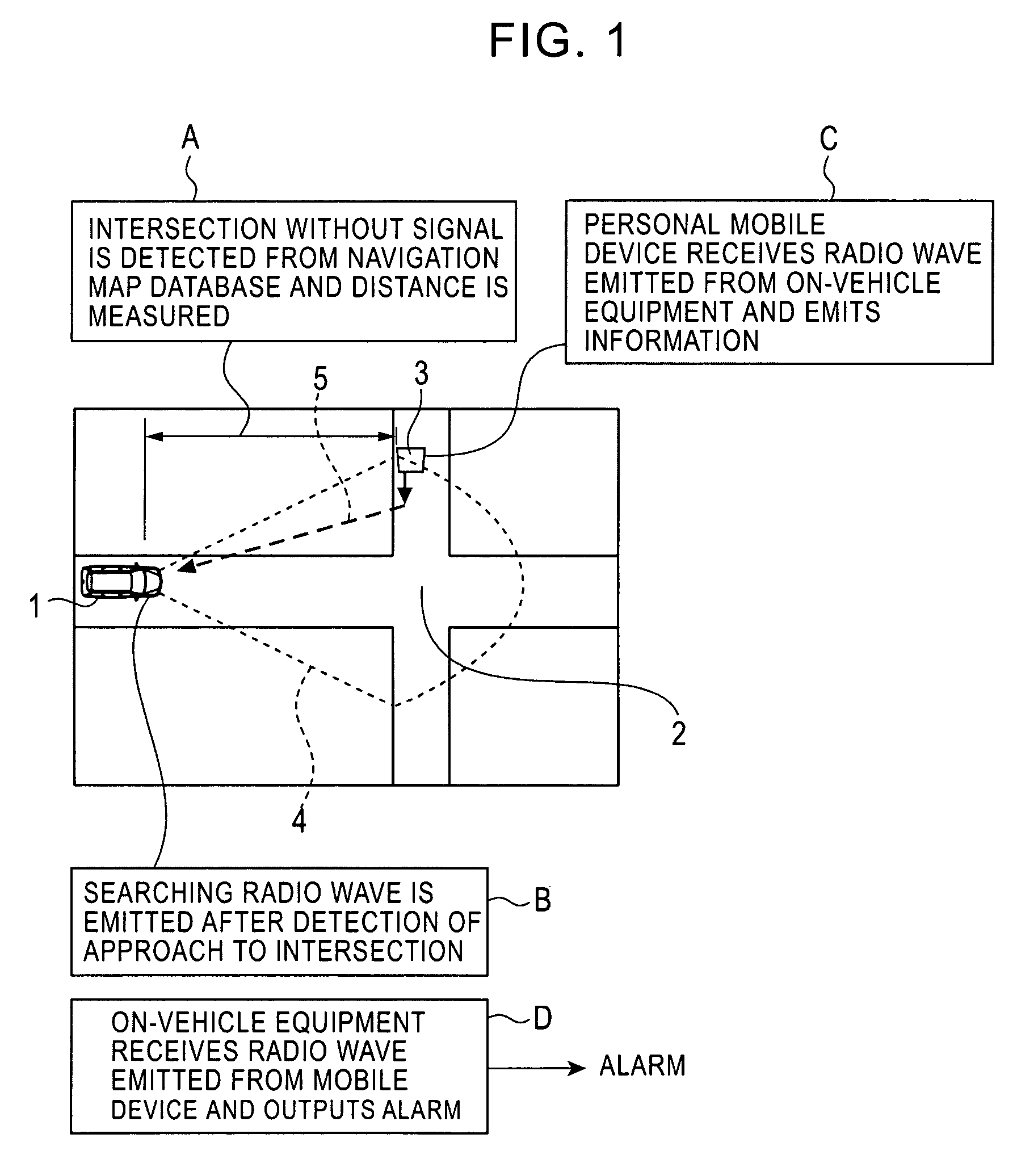
[0032]A searching-radio-wave emitting-point, i.e., a dangerous point, is previously registered in the searching-radio-wave emitting-point storing unit 11. In practice, the searching-radio-wave emitting-point is registered in map data stored in a map database used with a navigation system. For example, the dangerous point may be one of the following:[0033]an intersection without a traffic signal[0034]a poorly visible curve (specified on the basis of its curv...

second embodiment

[0047]FIG. 4 is a block diagram of the structure of an alarm generation apparatus according to a second embodiment of the present invention. A stepping-out passage point, i.e., a dangerous point, is previously registered in a stepping-out passage-point storing unit 11′. In practice, the stepping-out passage point is registered in map data stored in a map database used with a navigation system. The vehicle-position measuring unit 12 detects the vehicle position and provides it to the navigation controller 13. The navigation controller 13 displays a map on the monitor 14 with the aid of map data for the area around the vehicle position and monitors whether the stepping-out passage point exists in the vehicle's traveling direction. If the dangerous point exists, the navigation controller 13 computes a distance from the vehicle to the point. When the computed distance matches a set distance and the vehicle approaches the stepping-out passage point, the navigation controller 13 instructs...

third embodiment

[0057]With the alarm-generation apparatuses according to the second embodiment and its modification, the stepping-out passage point is previously registered in a navigation system, and the approach of the vehicle to the stepping-out passage point is detected. Instead of this arrangement, it is also possible that the approach of the vehicle to the stepping-out passage point is detected by photographing the stepping-out passage point with a camera and by analyzing a camera image.

[0058]FIG. 7 is a block diagram of an alarm-generation apparatus having such a structure. A camera 61 capable of continuous photography starts photographing a stepping-out passage point ahead, and the photographed image is stored in an image memory 62. An image-signal processing unit 63 applies image-signal processing to the camera image and extracts features of the image.

[0059]On the basis of the features of the image, a first image analyzing unit 64 detects the stepping-out passage point such as a utility po...


PUM


Abstract

An on-vehicle alarm generation method and an on-vehicle alarm generation apparatus for notifying a driver to be aware of safe driving by detecting a passerby or a bicycle moving at a dangerous point and generating an alarm to the driver are provided. In one aspect, the on-vehicle alarm generation method for detecting a passerby and generating an alarm to a driver includes the steps of including a dangerous driving point in map data and detecting the vehicle position; monitoring whether the vehicle approaches the dangerous driving point; transmitting a searching signal when the vehicle approaches the dangerous driving point; monitoring whether, in response to the searching signal, a responsive signal is received from a mobile device carried by the passerby; and generating an alarm to the driver upon receiving the responsive signal.

Description

BACKGROUND[0001]1. Field of the Invention[0002]The present invention relates to an alarm generation method and apparatus, and in particular, it relates to an alarm generation method and apparatus for generating an alarm to a driver of a vehicle.[0003]2. Description of the Related Art[0004]With a known technology (see Japanese Unexamined Patent Application Publication 11-232411), a searching radio wave is continuously emitted from on-vehicle equipment to a mobile device carried by a pedestrian or a cyclist. Upon receipt of the radio wave, the mobile device carried by the pedestrian or the cyclist increases its output power. Thus, a receiving device included in the on-vehicle equipment searches for the output power and detects the pedestrian or the cyclist. With this technology, a driver is accurately informed of the approach of a passerby on a poorly visible street or at a pedestrian-crossing and is assisted in performing safe driving.[0005]Unfortunately, the foregoing known technolo...

Claims


Application Information

Patent Timeline
Patent Type & Authority Patents(United States)
IPC IPC(8): B60Q1/00
CPCG01S13/931G08G1/162G01S2013/936G01S2013/9316
Inventor TAKATA, KAZUAKIMORI, DAISHI
Owner ALPINE ELECTRONICS INC
Learn More