Belt-drive control device, color-shift detecting method, color-shift detecting device, and image forming apparatus

a control device and control device technology, applied in the direction of electrographic process equipment, instruments, optics, etc., can solve the problems of lowering image quality, difficult to completely eliminate the speed fluctuation of the direct transfer conveying belt or intermediate transfer conveying belt, and position errors

Inactive Publication Date: 2008-05-20
RICOH KK
View PDF26 Cites 48 Cited by
  • Summary
  • Abstract
  • Description
  • Claims
  • Application Information

AI Technical Summary

Problems solved by technology

However, it is difficult to completely eliminate the speed fluctuation of the direct transfer conveying belt or intermediate transfer conveying belt although it can be reduced by means of feedback control.
A position error is acquired by performing the calculation for each control cycle and feedback control is performed.
However, this method causes changes in conveying speed of the transfer sheet or the intermediate transfer conveying belt due to a minute thickness of the endless belt, and causes lowering in image quality such as image deviation from an ideal position and positional displacement of an image among a plurality of recording sheets, resulting in deteriorated repetitive image position reproducibility among recording sheets.
When the belt thickness fluctuation occurs and the belt conveying speed is detected by the encoder based on the rotation angular displacement of the follower shaft, erroneous detection components are generated.
Therefore, in feedback control to detect the belt conveying speed based on the follower shaft rotation angular displacement as conventionally, the speed fluctuation due to fluctuation in thickness of the belt cannot be controlled.
However, in the above method, as speed profile data, data for each control cycle is needed, so that when the control cycle is short, a memory with a high capacity becomes necessary, and when the control cycle is set long, feedback control itself cannot show a sufficient effect.
Therefore, a separate memory is necessary in addition to the memory that has been used as a normal work area, and this results in a remarkable cost increase and is not realistic.
However, to measure the thickness fluctuation of several micrometers of the belt, a high-accuracy measuring unit is necessary, and data management and data amount of the measured results are large in size, and this may cause an input error.
In the color-shift detecting device, since speed fluctuation of the belt due to belt thickness fluctuation cannot be controlled by means of feedback control in that the belt conveying speed is detected based on the conventional follower shaft rotation angular displacement, the fluctuation harmfully influences the color shift correction accuracies and causes image deterioration.
Namely, the belt speed when mark sets for color shift correction are drawn on the belt and the belt speed when the mark sets are detected are different from the belt speed when images are actually drawn on the belt, resulting in color shifts.
However, in this case, the length of all groups of mark sets may become long, the color shift correction time may become slightly long, or the toner consumption may slightly increase.
Furthermore, if the execution timing of color shift detection and correction is only either one of an execution timing instructed through an operation panel or an automatic execution timing, image quality that a customer desires cannot be provided in a desired timing in some cases.
However, if calculation of the phase and maximum amplitude to be stored in the nonvolatile memory is performed by only either one of manual execution or automatic execution, in some cases, image quality that a customer desires cannot be provided in a desired timing.
Particularly, when the phase and maximum amplitude of the angular displacement error change due to aging of the belt, color shift detection and correction makes worse the color shifts unless the calculation is performed.

Method used


Image

  • Belt-drive control device, color-shift detecting method, color-shift detecting device, and image forming apparatus
  • Belt-drive control device, color-shift detecting method, color-shift detecting device, and image forming apparatus
  • Belt-drive control device, color-shift detecting method, color-shift detecting device, and image forming apparatus

Examples


Embodiment Construction

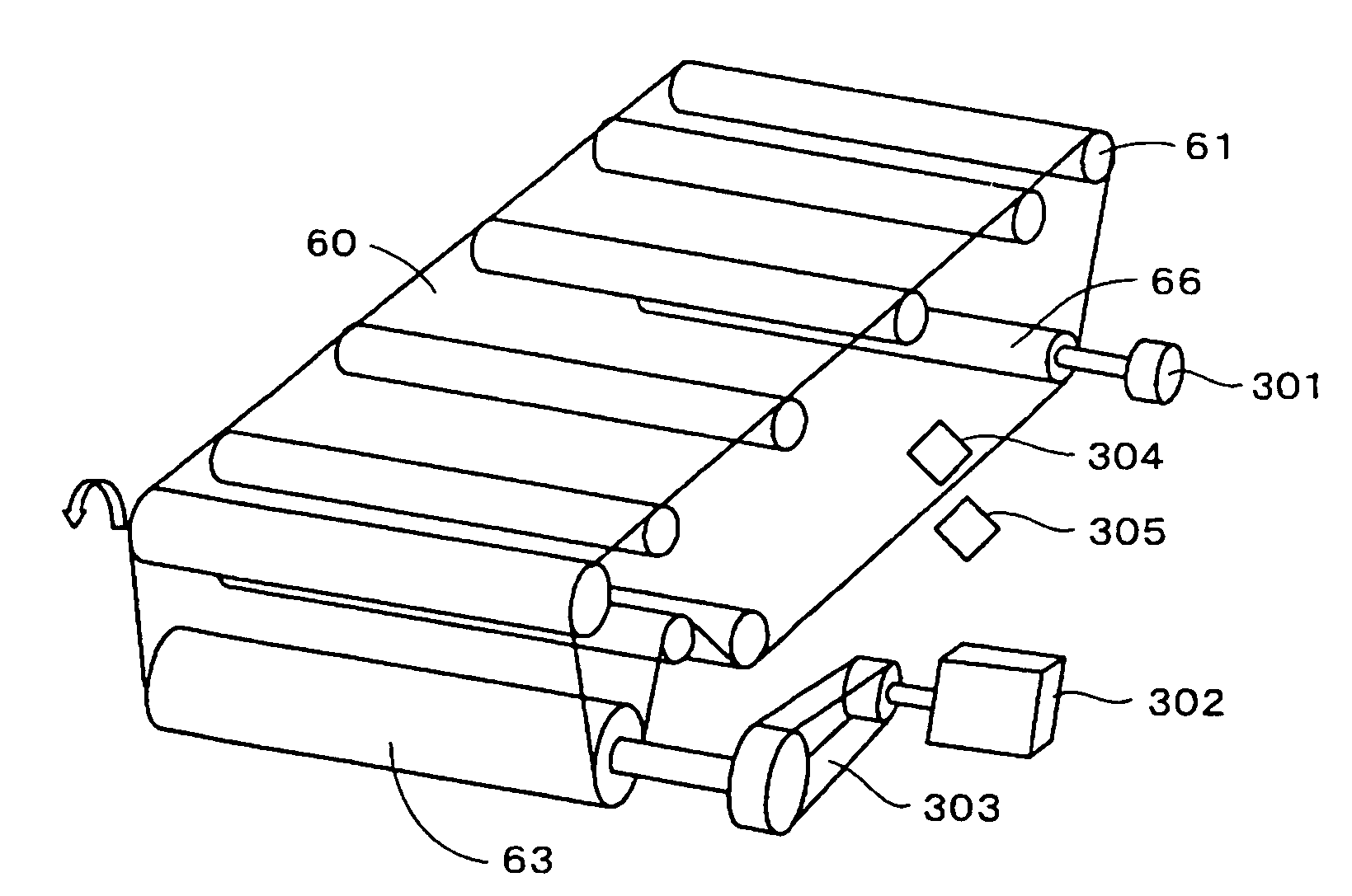
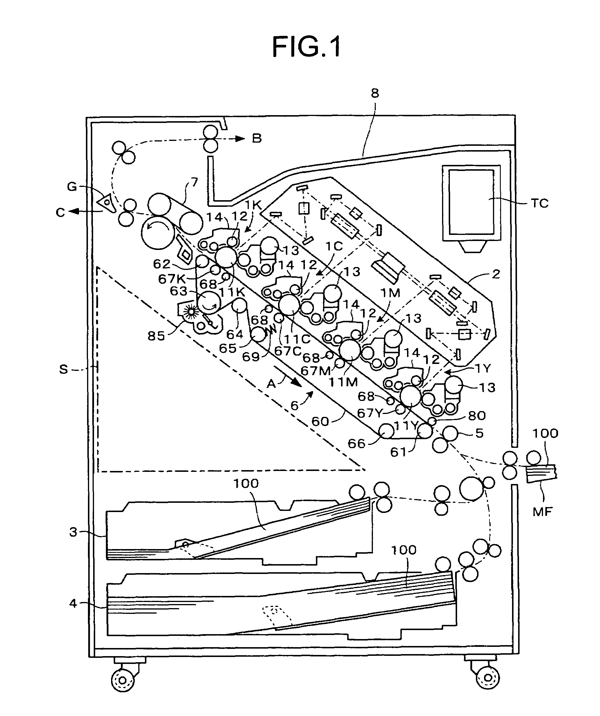
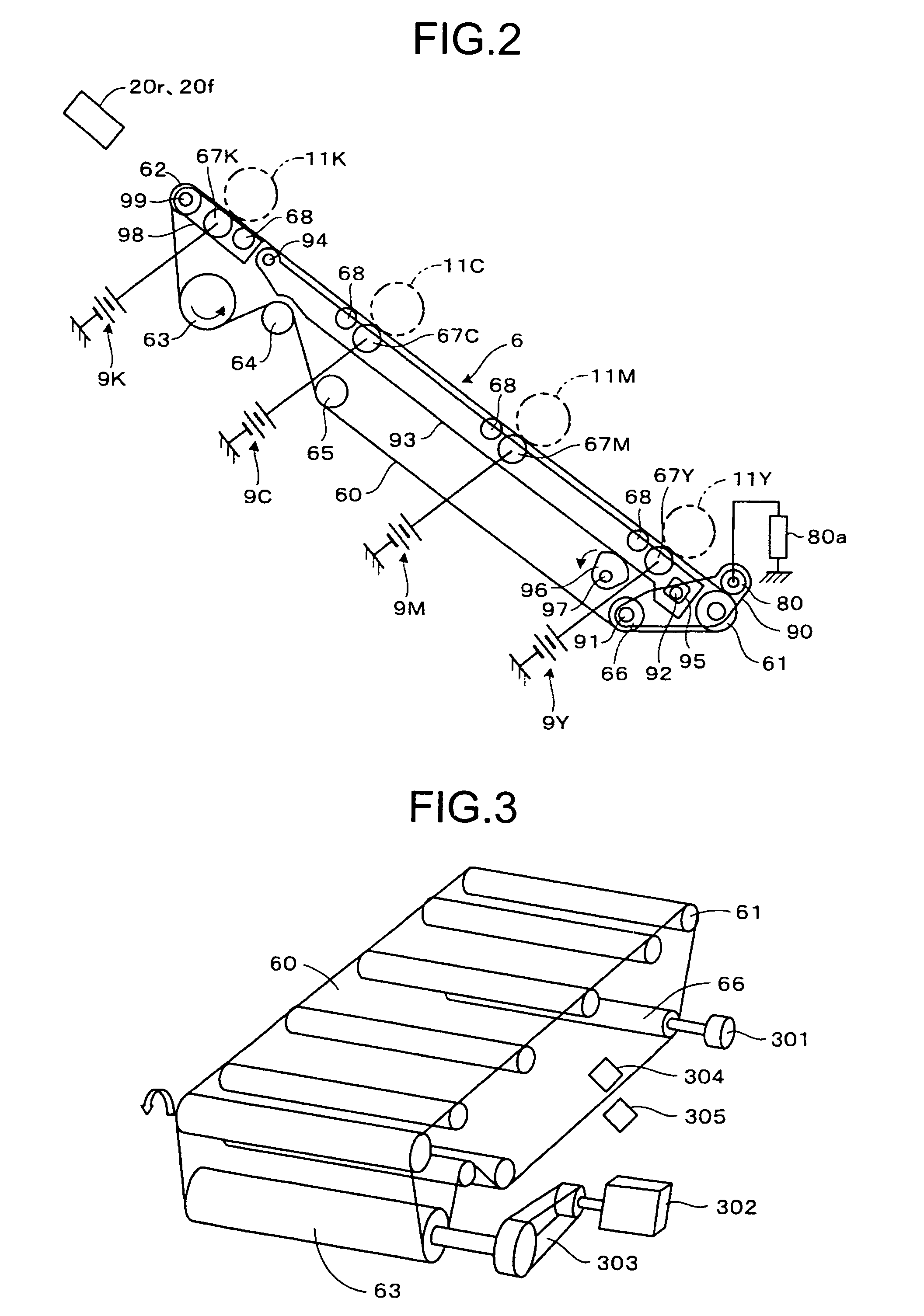
[0091]Exemplary embodiments of the present invention are explained in detail below with reference to the accompanying drawings. An example in which the present invention is applied to a color laser printer (hereinafter, “laser printer”) employing an electrophotographic direct transfer method as an image forming apparatus is explained with reference to FIGS. 1 and 2.

[0092]FIG. 1 depicts the laser printer of the present embodiment. In this laser printer, four toner image forming units 1Y, 1M, 1C, and 1K (hereinafter, Y, M, C, and K attached to these symbols indicate the yellow, magenta, cyan, and black members, respectively) for forming images in colors of yellow (Y), magenta (M), cyan (C), and black (K) are arranged in order from the upstream side in the moving direction (traveling direction of a transfer conveying belt 60 as a direct transfer conveying belt along the arrow A of the figure) of a transfer sheet 100. The toner image forming Units 1Y, 1M, 1C, and 1K include photoconduct...


PUM


Abstract

A mark detecting unit detects a mark that is a reference position of an endless belt. An angular-displacement-error detecting unit detects an angular displacement error of an encoder caused by thickness fluctuation of the endless belt. A first calculating unit calculates a phase and a maximum amplitude to the mark. A second calculating unit calculates correction data according to a distance from the mark on the endless belt. A belt-drive control device controls a belt driving unit by adding the correction data to a preset control target value to stabilize speed fluctuation of the endless belt due to the thickness fluctuation.

Description

CROSS-REFERENCE TO RELATED APPLICATIONS[0001]The present document incorporates by reference the entire contents of Japanese priority documents, 2005-017418 filed in Japan on Jan. 25, 2005 and 2005-189777 filed in Japan on Jun. 29, 2005.BACKGROUND OF THE INVENTION[0002]1. Field of the Invention[0003]The present invention relates to a belt-drive control device, a color-shift detecting method, a color-shift detecting device, and an image forming apparatus.[0004]2. Description of the Related Art[0005]In an image forming apparatus, as described in Japanese Patent Application Laid-Open No. 2000-310897, when a transfer conveying belt is rotated by driving a drive roller at a fixed pulse rate, based on a position to be detected due to a belt mark on the transfer conveying belt, a speed profile that cancels a speed fluctuation Vh expected to occur due to a known thickness profile across the whole circumference of the transfer conveying belt is measured in advance, and at a pulse rate modulat...

Claims


Application Information

Patent Timeline
Patent Type & Authority Patents(United States)
IPC IPC(8): G03G15/00
CPCG03G15/1685G03G2215/00156G03G2215/0016G03G2215/1623
Inventor KOBAYASHI, KAZUHIKOMATSUDA, HIROMICHIANDOH, TOSHIYUKIYOKOKAWA, NOBUTOIMAI, RYOJIMATSUDA, YUJIOKAMURA, HIROSHIYOKOYAMA, MASATOMIURA, YOHEI
Owner RICOH KK
Why Eureka
Try Eureka