Color shift correcting method, optical writing device and image forming apparatus

Inactive Publication Date: 2004-05-27
RICOH KK
View PDF35 Cites 55 Cited by
  • Summary
  • Abstract
  • Description
  • Claims
  • Application Information

AI Technical Summary

Problems solved by technology

However, image formation at an increased speed can result in inaccurate color registration of images formed by the respective image forming units, so that it is quite difficult to reconcile a higher image quality and faster processing.
This difficulty is caused by the position and size of each image forming unit which forms part of the color image forming apparatus, and by a subtle change in the position and size of parts in the image forming units.
However, since the optical deflector is rotating at a high speed, the phase adjustment takes a long time and entails technical difficulties, and therefore causes a prohibitively high cost in actuality.
Thus, if a misregistration for each color is corrected only with the write timing, the misregistration during one scanning operation of the deflector cannot be corrected in theory.
However, even if the information sensed by the encoder is relied on to reduce fluctuations in the rotation of the photosensitive drum, the photosensitive drum itself includes eccentricities, or the surface of the ph

Method used


Image

  • Color shift correcting method, optical writing device and image forming apparatus
  • Color shift correcting method, optical writing device and image forming apparatus
  • Color shift correcting method, optical writing device and image forming apparatus

Examples


first embodiment

[0081] 1.

[0082] 1.1 General Configuration of Image Forming Apparatus:

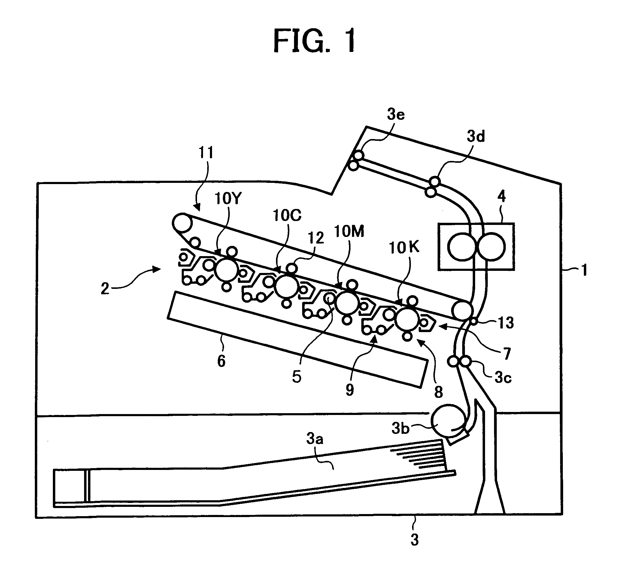
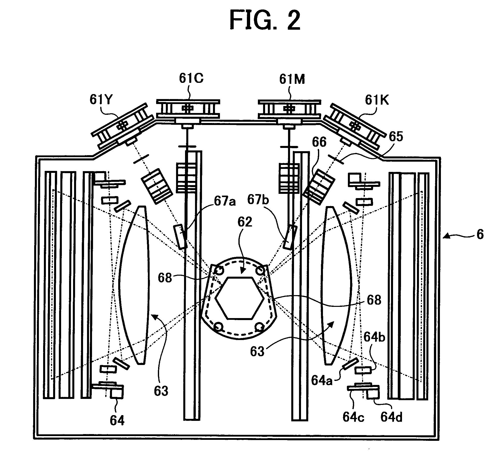
[0083] FIG. 1 generally illustrates the configuration of a color laser printer which embodies an image forming apparatus according to a first embodiment, FIG. 2 is a plan view of an optical writing (exposure) apparatus, and FIGS. 3 and 4 are cross-sectional views generally illustrating the optical writing (exposure) apparatus.

[0084] Referring first to FIG. 1, the color laser printer 1, which embodies the image forming apparatus, employs a photoelectric image forming process and basically comprises an image generator block 2, a sheet feeder block 3 including a sheet feeder cassette 3a, and a fixer block 4. The image generator block 2 includes a plurality of photosensitive drums 10, a plurality of exposure units 6, a plurality of transfer units 5, and the like. The photosensitive drums 10 (10Y, 10C, 10M, 10K) are provided with charging units 8 (8Y, 8C, 8M, 8K), exposure units 6 (6Y, 6C, 6M, 6K), transfer units 5 (5Y,...

second embodiment

[0134] 2.

[0135] 2.1 General Configuration and Control Scheme of Image Forming Apparatus:

[0136] In a second embodiment, a photosensitive drum reference position mark 23 is attached on one of the photosensitive drums 10 in the first embodiment, as shown in FIG. 15, and a reference position sensor 24 is provided for detecting the photosensitive drum reference position mark 23 to correct a color shift. Thus, the second embodiment differs from the first embodiment in that the beam position is controlled based on the photosensitive drum reference position mark 23 and the output of the reference position sensor 24. Since the rest of the configuration in the second embodiment is equivalent to that of the first embodiment, like parts are designated the same reference numerals, and repeated description thereon is omitted.

[0137] FIG. 15 generally illustrates the structure of a driving mechanism for rotating the photosensitive drums 10Y, 10C, 10M, 10K and the intermediate transfer belt 11 in th...

third embodiment

[0155] 3.

[0156] 3.1 General Configuration and Control Scheme of Image Forming Apparatus:

[0157] As illustrated in FIG. 20, in a third embodiment, a belt reference position mark 40 is provided on the intermediate transfer belt 11, and a belt reference position sensor 39 is provided for detecting the belt reference position mark 40 to correct a color shift. Except for the control based on the belt reference positron mark 40 and the output of the belt reference position sensor 39, the third embodiment is similar to the first embodiment in the remaining configuration, so that like parts are designated the same reference numerals, and repeated description thereon is omitted.

[0158] FIG. 20 generally illustrates the structure of a driving mechanism for rotating the photosensitive drums 10Y, 10C, 10M, 10K and intermediate transfer belt 11 in the image generator block 2 according to the third embodiment. As can be seen from FIG. 20, in addition to the driving mechanism illustrated in FIG. 9 i...


PUM


Abstract

A color shift correcting method for correcting a color shift due to misregistration of images in different colors, where a multi-color image is formed by developing latent one-color images written onto respective image carriers by an optical writing device, and directly or indirectly transferring developed one-color images onto a movable element, said method comprising the step of: adjusting a position at which one of said image carriers is irradiated with an optical beam in a sub-scanning direction to correct said color shift while said optical beam is irradiated from said optical writing device onto said image carriers to develop the latent one-color images.

Description

[0001] 1. Field of the Invention[0002] The present invention relates to a color shift correcting method for correcting a color shift, which can occur when an image is formed in a plurality of colors. More specifically, the present invention relates to a color shift correcting method for reducing a color shift, which can occur when a color image is formed by transferring a plurality of images sequentially formed in different colors (by a multi-image forming apparatus comprising a plurality of image forming means such as a tandem type color copier and a color printer, or by at least one image forming means) onto a transfer belt, a sheet on a transfer belt, or an intermediate transfer drum. The present invention also relates to an optical writing device and an image forming apparatus for use with the color shift correcting method.[0003] 2. Description of the Related Art[0004] In recent years, colorization has been rapidly introduced into documents processed in businesses, so that image...

Claims


Application Information

Patent Timeline
IPC IPC(8): B41J2/44G03G15/00G03G15/01G03G15/04G03G15/16H04N1/036H04N1/04H04N1/047H04N1/06H04N1/113H04N1/50
CPCG03G2215/0119G03G15/0194G03G2215/0158H04N1/0473H04N1/06H04N1/1135H04N1/506H04N2201/0471H04N2201/04786G03G2215/0132G03G15/011H04N2201/04722H04N2201/04732H04N2201/04793G03G15/01
Inventor BANNAI, KAZUNORIYAMAZAKI, KOZO
Owner RICOH KK
Why Eureka
Try Eureka