
Coiled tubing counter

a counter and coiled tubing technology, applied in the direction of measuring wheels, surveying, borehole/well accessories, etc., can solve the problems of counters being exposed to various abuse, and counters being prone to errors

Inactive Publication Date: 2008-05-27
COUNT RITE OILFIELD SOLUTIONS
View PDF16 Cites 7 Cited by
  • Summary
  • Abstract
  • Description
  • Claims
  • Application Information

AI Technical Summary

Benefits of technology

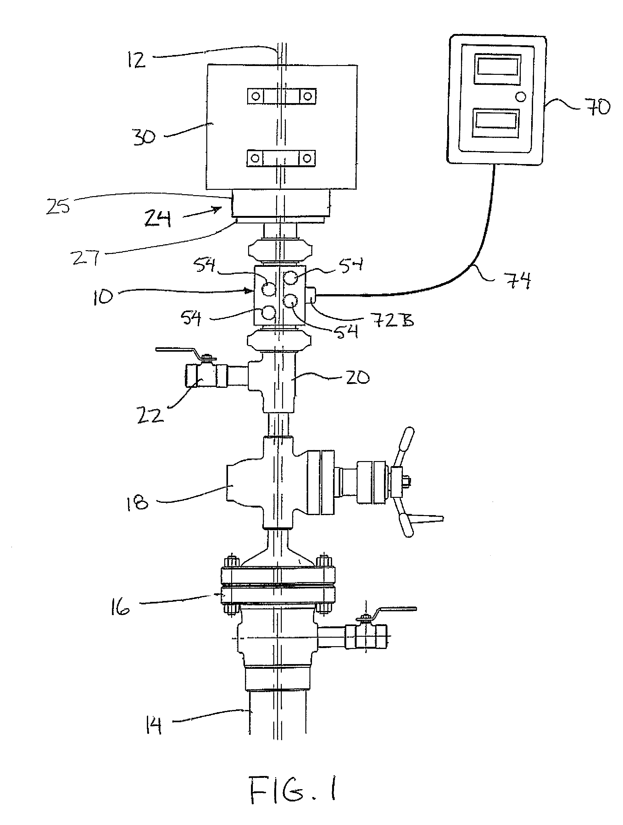
[0012]Use of a housing which can be connected with pressure rated connectors permits installation of the counter in series between the outer casing of the well and the injector head. The resulting counter provides a simple mechanism which is independent of the mechanisms of the injector head and which is protected within an enclosed housing. Locating the counter below the injector head and below the tubing stripper ensures that the tubing is cleaner and less likely to slip in contact with the counting wheels. Furthermore, location of the counter below the injector head accounts for stretching of the tubing for more accurate measurement of depth.
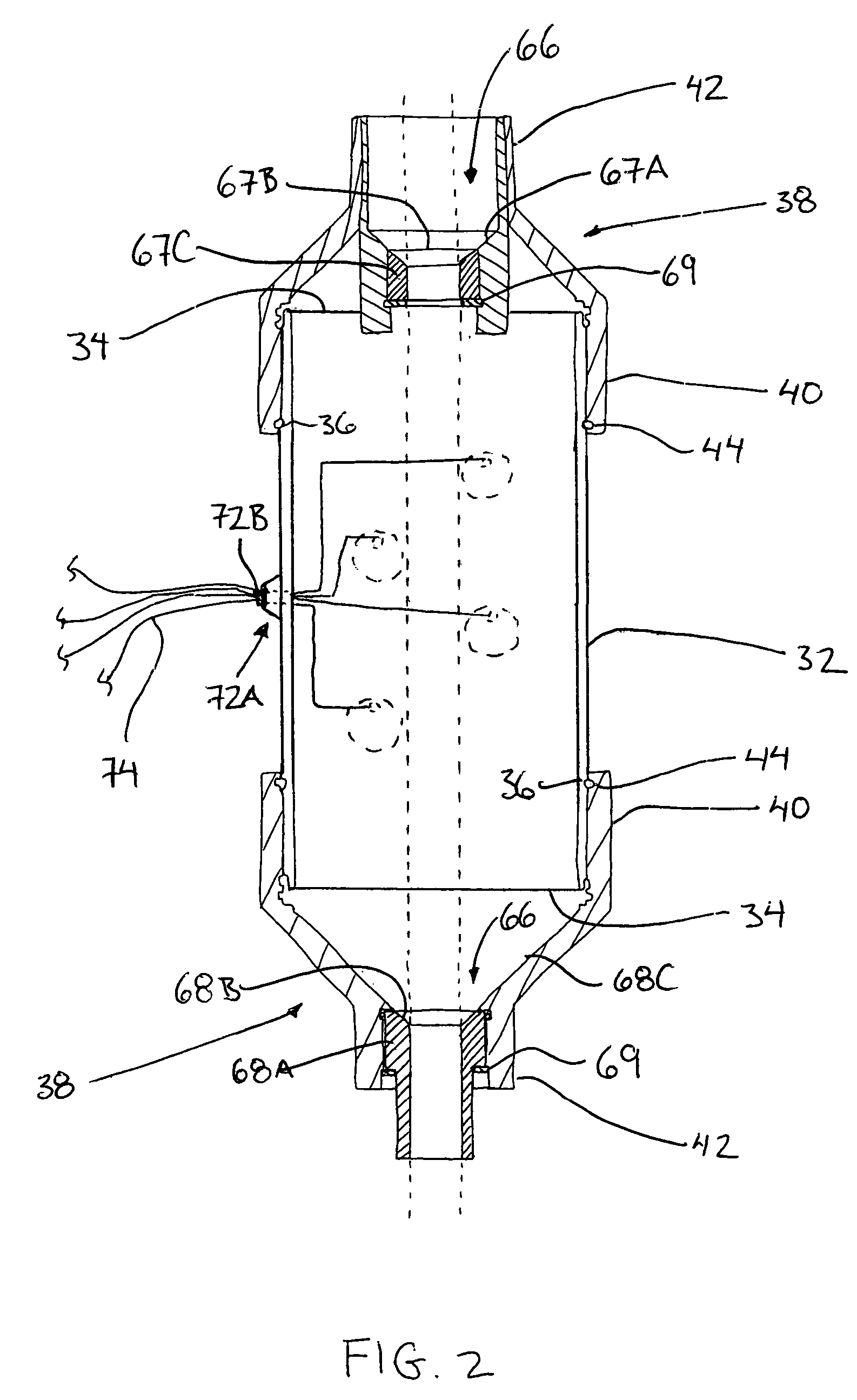
[0018]Use of a plurality of counting wheels which independently record a number of rotations ensures that any slippage errors can be readily identified regardless of whether the counter is positioned above or below the injector head.

Problems solved by technology

When counters are connected above the injector head, the counters are prone to errors due slippage on the tubing which is dirty and exposed to the environment.
These counters are therefore typically unable to account for the errors due to slippage between the counting wheel and the tubing upon which the counting wheel is riding.
Also, these counters are simply transported on the exterior of trucks in a manner such that they are exposed to various abuse during use and transport.
Furthermore, positioning of the counter above the injector head does not take into consideration how much the tubing stretches and accordingly these types of counters are also inaccurate in addition to requiring considerable maintenance.
Counters which are supported in conjunction with the injector head typically rely on a mechanical connection to the components of the injector head which may be subject to failure due to the complexity of the mechanisms required.
These types of counters are also unable to accommodate for stretch of the tubing suspended below the injector head and accordingly are also inaccurate.

Method used


Image

  • Coiled tubing counter
  • Coiled tubing counter
  • Coiled tubing counter

Examples


Embodiment Construction

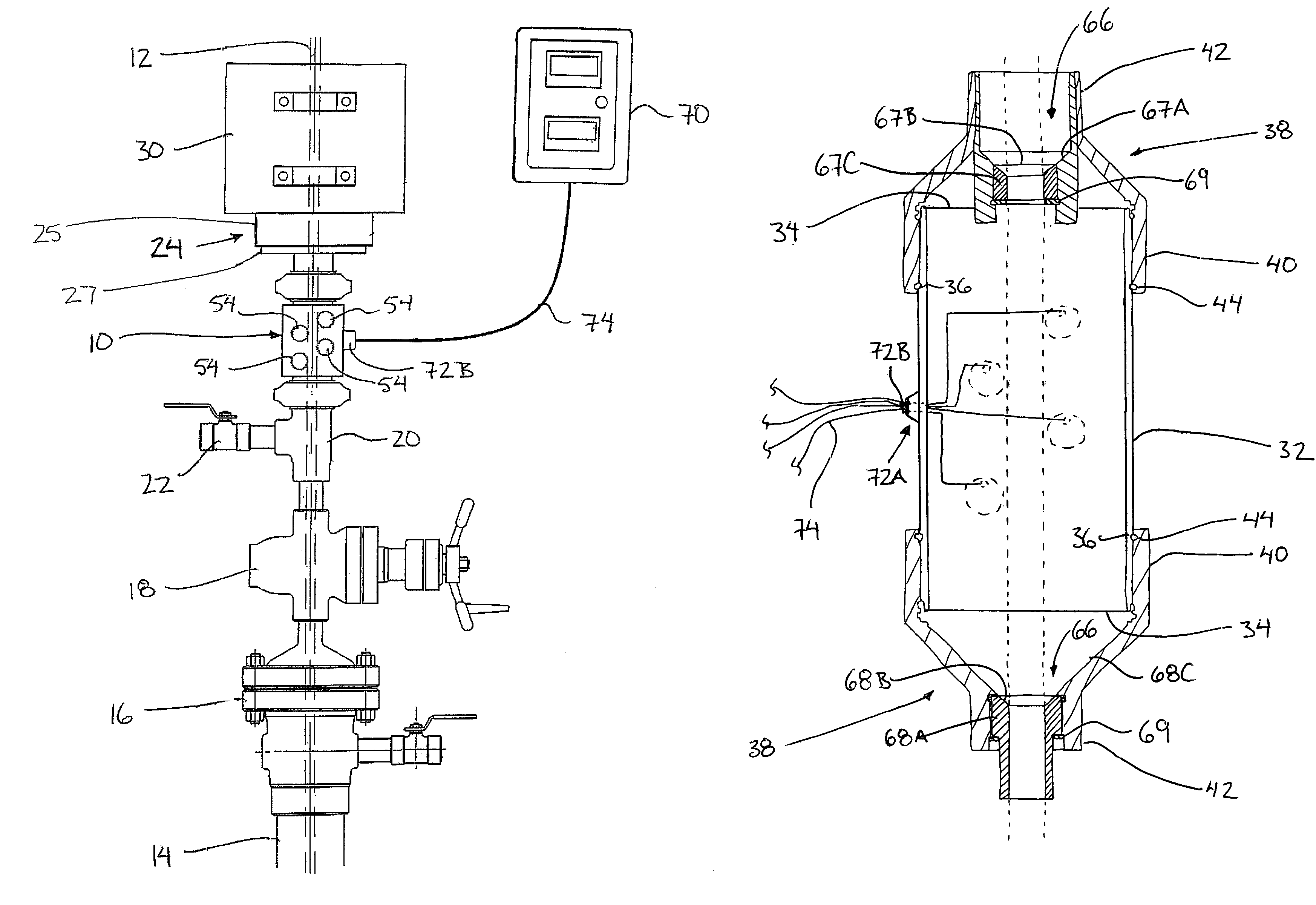
[0044]Referring to the accompanying Figures there is illustrated a coiled tubing counter generally indicated by reference numeral 10. The counter 10 is particularly suited for oil or gas well operations involving coiled tubing 12 for counting the depth which the tubing is inserted into the well.

[0045]The counter 10 is typically used in an oil or gas well having an outer casing 14 terminating at a top end by a casing flange 16 which may connect a master valve 18, a flow tee 20 having an auxiliary valve 22 and a primary well control 24 which includes a stripper 25 and a blow out preventer (BOP) as components of the wellhead. A coiled tubing injector head 30 is connected above the primary well control 24. All of the wellhead components below the injector head, including the primary well control 24 are sealed with respect to the outer casing in such a manner so as to permit the components between the primary well control 24 and the outer casing to be pressurized.

[0046]Referring initiall...


PUM


Abstract

A tubing counter for counting coiled tubing inserted into a well includes an outer housing having a through passage for receiving the coiled tubing therethrough. In some embodiments, pressure rated connectors at both of the ends of the outer housing sealably connect the outer housing in series between the coiled tubing injector head and the outer casing of the well. A plurality of counting wheels are rotatably supported within the outer housing for rolling engagement along coiled tubing inserted through the outer housing while a counting mechanism records a number of rotations of each counting wheel independently of the other wheels to minimize counting errors. Locating the counter below the injector head and below the tubing stripper ensures that the tubing is cleaner and less likely to slip in contact with the counting wheels while also accounting for stretching of the tubing for more accurate measurement.

Description

[0001]This application claims foreign priority benefits from Canadian Patent Application 2,506,446 filed May 6, 2005.FIELD OF THE INVENTION[0002]The present invention relates to a counter for counting coiled tubing, and more particularly relates to a counter for counting the coiled tubing as it is inserted into an oil or gas well.BACKGROUND[0003]In the field of oil and gas production various activities related to wells involve the insertion of coiled tubing into the wells. Coiled tubing is typically dispended from a roll supported on a rig which inserts the tubing into the casing of the well by a coiled tubing injector head supported above the casing. When inserting the tubing, it is desirable to count the length of tubing being inserted so as to know the depth of insertion of the bottom end of the tubing.[0004]Various types of counters are known for strand material, including cable or tubing and the like. Typical counters make use of wheels which roll along the strand material as i...

Claims


Application Information

Patent Timeline
Patent Type & Authority Patents(United States)
IPC IPC(8): G01B3/12
CPCE21B19/22E21B47/04
Inventor MORRIS, COLLIN RICKEYRECK, JOSEPH HENRYBOYD, DOUGLAS GLENVAN DRECHT, SHAWN RODNEY
Owner COUNT RITE OILFIELD SOLUTIONS
Learn More