Double clutch transmission

a transmission and clutch technology, applied in mechanical equipment, transportation and packaging, gearing, etc., can solve the problems of high torque load on all components which follow in the force flux, sharp increase, etc., and achieve the effect of reducing wear

Inactive Publication Date: 2008-05-27
DAIMLER AG
View PDF23 Cites 27 Cited by
  • Summary
  • Abstract
  • Description
  • Claims
  • Application Information

AI Technical Summary

Benefits of technology

[0011]In an especially advantageous refinement of the invention, the double clutch transmission has an odd number of forward gears, the first forward gear being a winding-path transmission gear, wherein the power path through the transmission may switch between the main transmission shaft and the counter shaft several times. In particular, seven forward gears may be provided as an odd number of forward gears. This refinement avoids the following dilemma which occurs when the first and the highest forward gears are implemented via the same input gear set. Without a winding-path first forward gear, a first possibility for the transmission design would be to design the respective input transfer or transmission gear set to be very short in a disadvantageous way, so that, overall, a sufficiently short first forward gear, that is, a sufficiently high transmission ratio is obtained. The second transfer of the highest forward gear would then disadvantageously have to be designed to be very long, so that a sufficient spread is obtained or this highest forward gear has, overall, a sufficiently long transfer. Furthermore, owing to the short input transfer or transmission constant, the torque is disadvantageously increased sharply already in the first transfer stage, so that all the components which follow in the force flux are subjected to a high torque load. If, in contrast to the first possibility, the respective input transfer is designed to be relatively long, so that the second transfer stage of the highest forward gear does not have to be extremely long, it is necessary, however, to design the second transfer stage of the first forward gear to be extremely short, so that, overall, a first forward gear with a sufficiently short transfer ratio is obtained.
[0025]During the change from the power flux into the load-free part transmission, a shift clutch can be left engaged, even though this is not absolutely necessary for the gear currently selected. When this shift clutch left engaged outside the power flux is then required again in a subsequent forward shift or backshift, this shift clutch does not have to be actuated. Shifts can consequently be carried out especially quickly and with reduced wear. This method may be employed both in reverse and forward gears and also during the change between forward and reverse gears.

Problems solved by technology

The second transfer of the highest forward gear would then disadvantageously have to be designed to be very long, so that a sufficient spread is obtained or this highest forward gear has, overall, a sufficiently long transfer.
Furthermore, owing to the short input transfer or transmission constant, the torque is disadvantageously increased sharply already in the first transfer stage, so that all the components which follow in the force flux are subjected to a high torque load.

Method used


Image

  • Double clutch transmission
  • Double clutch transmission
  • Double clutch transmission

Examples


first embodiment

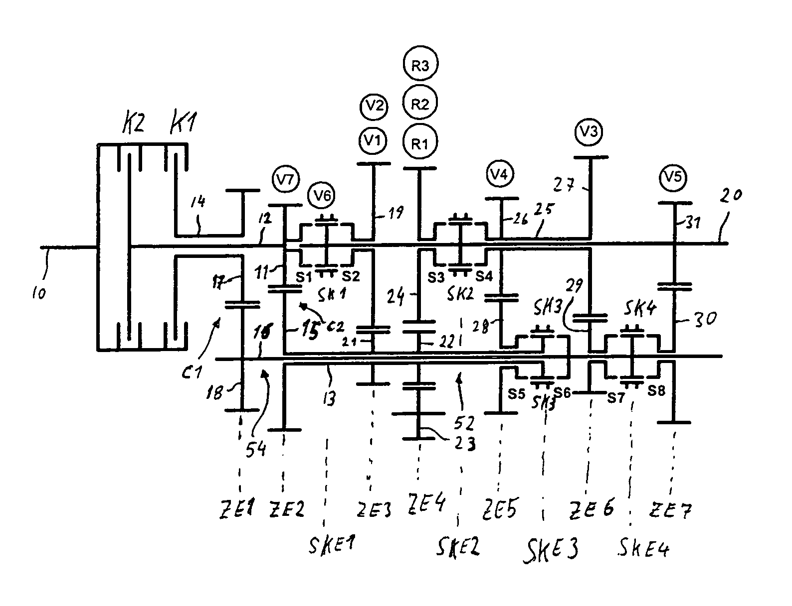
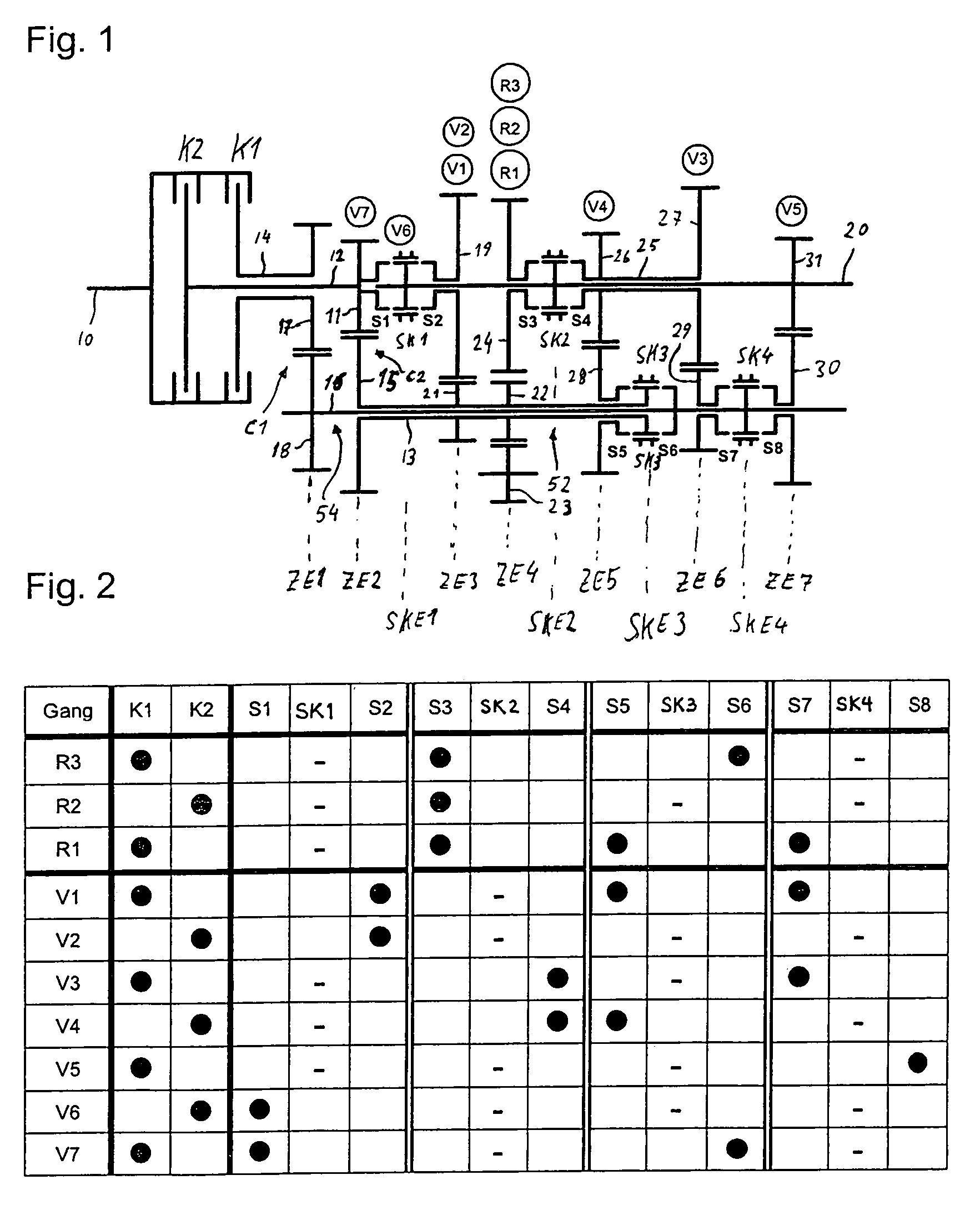
[0052]FIG. 1 shows a double clutch transmission in a first embodiment, which is used in a rear drive or multi-axle drive of a motor vehicle, the engine and double clutch transmission of which are installed longitudinally in the direction of travel. This motor vehicle may be, in particular, a high-torque passenger car or a commercial vehicle.

[0053]In the double clutch transmission, an input shaft 10 is connected to a transmission output shaft 20 by means of a first part transmission 54 and a second part transmission 52. The two part transmissions 52 and 54 are arranged parallel to one another in the power flux. The part transmissions 52, 54 possess in each case a power-shift friction clutch K1, K2 and in each case an intermediate shaft 12, 14, of which the first intermediate shaft 14 is designed as a radially outer hollow shaft and the second intermediate shaft 12 as a radially inner intermediate shaft 12. The intermediate shafts 12, 14 are arranged[0054]concentrically with respect t...

second embodiment

[0208]FIG. 13 shows a double clutch transmission in a

[0209]The construction of this double clutch transmission is identical, from the front as far as the third shift clutch plane SKE3 to the first embodiment, and therefore reference to the latter is made here.

[0210]However, a fourth shift clutch SK4 is arranged coaxially with respect to the transmission input shaft 20. By means of this shift clutch SK4, on the one hand, in a position S7, a gearwheel 27 arranged rotatably and coaxially on the second hollow shaft 25 in a sixth gearwheel plane ZE6 can be connected fixedly in terms of rotation to the hollow shaft 25. On the other hand, in a position S8, an axially adjacent gearwheel 31 arranged rotatably and coaxially on the transmission output shaft 20 in a seventh gearwheel plane ZE7 can be connected fixedly in terms of rotation to the transmission output shaft 20.

[0211]A fixed wheel 29 arranged coaxially and fixedly in terms of rotation on the inner shaft 16 meshes with the gearwheel...

third embodiment

[0214]FIG. 15 shows a double clutch transmission in a

[0215]The construction of this double clutch transmission is identical, from the front as far as the third shift clutch plane SKE3, to the first and the second embodiment, and therefore reference is made here, in this respect, to both of these. As regards the seventh gearwheel plane ZE7, reference is made to the second embodiment since this is identical in the region of the seventh gearwheel plane ZE7.

[0216]In contrast to the preceding embodiments, only two intermeshing gearwheels are arranged in the gearwheel plane ZE4 assigned to the single reverse gear R1. One of these two gearwheels is a loose wheel 22 which is arranged rotatably and coaxially on the first hollow shaft 13. The other gearwheel is an intermediate wheel 23 which, in contrast to the preceding exemplary embodiments, does not have a direct output to a gearwheel in the fourth gearwheel plane ZE4, but, by means of a second intermediate wheel 33, has an output via a co...


PUM


Abstract

In a double clutch transmission with a winding path power flux arrangement, which has two countershafts arranged coaxially with respect to one another and with seven forward gears and a plurality of reverse gears, for selected gears the power flux extends from a part region of the transmission forward and then again back to another part region of the transmission in such a way that only four shift clutches are needed for shifting through all the gears.

Description

[0001]This is a Continuation-In-Part Application of International Application PCT / EP2004 / 008976 filed 11 Aug. 2004 and claiming the priority of German application 103 39 758.2 filed 27 Aug. 2003.BACKGROUND OF THE INVENTION[0002]The invention relates to a double clutch transmission, which has two countershafts arranged coaxially with respect to one another, and to a method of shifting such a transmission.[0003]Such a double clutch transmission is already known from the publication by Tenberge, P.: “Doppelkupplungsgetriebe in Windungsanordnung” [“Double clutch transmission in a winding arrangement”], VDI-Seminar No. 31 03 01 “Stufenlose Fahrzeuggetriebe” [“Continuously variable vehicle transmissions”], Stuttgart, 2001.[0004]DE 103 25 647 A1, not yet published, likewise already shows a double clutch transmission in a winding arrangement. In this, however, the countershafts are arranged parallel to one another.[0005]Furthermore, double clutch transmissions are known from EP 0 883 785 B1...

Claims


Application Information

Patent Timeline
Patent Type & Authority Patents(United States)
IPC IPC(8): F16H3/08F16H3/00F16H3/097
CPCF16H3/006F16H3/097F16H2003/0826Y10T74/19233F16H2200/0056F16H2200/0091Y10T74/19228F16H2003/0933
Inventor GITT, CARSTEN
Owner DAIMLER AG
Why Eureka
Try Eureka