Variable choke valve

a valve and valve body technology, applied in the direction of wellbore/well accessories, fluid removal, sealing/packing, etc., can solve the problems of affecting the sealing integrity of the entire production tubing conduit, and a possible loss of sealing integrity

Inactive Publication Date: 2008-05-27
WEATHERFORDLAMB
View PDF65 Cites 30 Cited by
  • Summary
  • Abstract
  • Description
  • Claims
  • Application Information

AI Technical Summary

Problems solved by technology

Thus, if the sealing element should fail, the tool cannot be effectively closed.
Further, such failure could adversely affect the sealing integrity of the entire production tubing conduit.
As with all seals, such primary sealing means also represent an area of possible loss of sealing integrity.

Method used


Image

  • Variable choke valve
  • Variable choke valve
  • Variable choke valve

Examples


Embodiment Construction

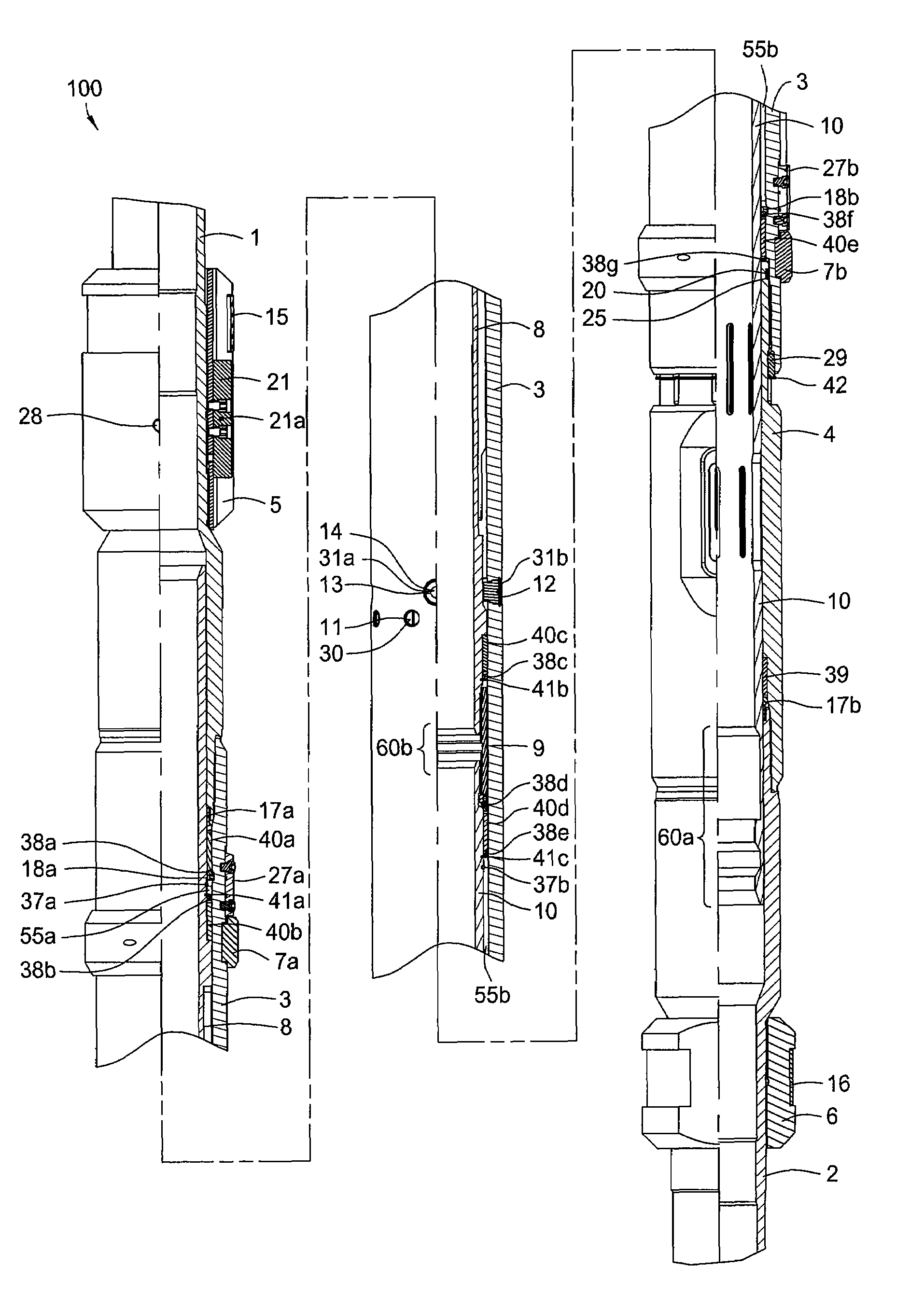
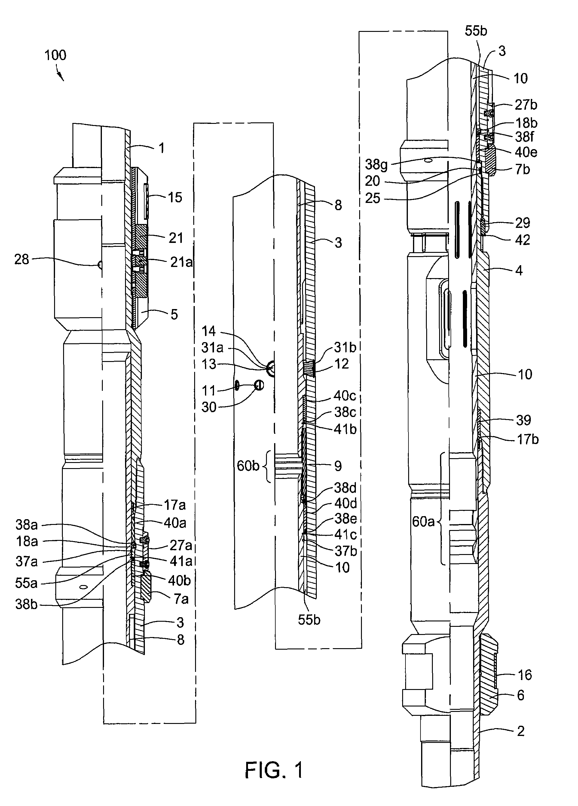
[0032]Descriptors of various parts of a variable choke valve 100, described below, implying a specific orientation, i.e. upper and lower, are meant for use relative to a vertical wellbore and are not meant to limit usage of the valve in any way. The valve may also be used in deviated, i.e. horizontal, wellbores where the descriptors would lose meaning. The valve may also be used upside down. Except for sealing members and unless otherwise specified, the choke valve 100 is made from a metal, such as steel.

[0033]FIG. 1 is a half-sectional / half-side view of the assembled variable choke valve 100. The variable choke valve 100 includes a top sub 1. The top sub 1 is a tubular member having a flow bore therethrough. At an upper end, the top sub 1 may include threads for coupling the variable choke valve 100 to a string of tubulars for insertion into a wellbore (not shown). Coupled to the top sub 1 along a middle portion of the top sub 1 by a threaded connection is an upper termination sub ...


PUM


Abstract

Embodiments of the present invention generally provide a more reliable variable choke flow control valve. In one embodiment, a variable choke valve for use in a wellbore is provided. The valve includes a tubular housing having an axial bore therethrough and a port through a wall thereof. The valve further includes a tubular sleeve having an axial bore therethrough and first and second holes through a wall thereof and disposed within the housing. The first hole is larger than the second hole, and the sleeve is actuatable among three positions: a first position where the first hole is aligned with the port, a second position where the second hole is aligned with the port, and a third position where the sleeve wall is aligned with the port.

Description

CROSS REFERENCE TO RELATED APPLICATIONS[0001]U.S. patent application Ser. No. 10 / 748,695, entitled “Seal Stack for Sliding Sleeve”), filed Dec. 30, 2003 is herein incorporated by reference.BACKGROUND OF THE INVENTION[0002]1. Field of the Invention[0003]Embodiments of the present invention generally relate to valves for use in wellbores.[0004]2. Description of the Related Art[0005]Subsequent to the drilling of an oil or gas well, the well is completed by running into such well a string of casing which is cemented in place. Thereafter, the casing is perforated to permit the fluid hydrocarbons to flow into the interior of the casing and subsequently to the top of the well. Such produced hydrocarbons are transmitted from the production zone of the well through a production tubing or work string which is concentrically disposed relative to the casing.[0006]In many well completion operations, it frequently occurs that it is desirable, either during the completion, production, or workover ...

Claims


Application Information

Patent Timeline
Patent Type & Authority Patents(United States)
IPC IPC(8): E21B33/12E21B34/00
CPCE21B34/10E21B34/06E21B43/12
Inventor JACKSON, STEPHEN L.
Owner WEATHERFORDLAMB
Why Eureka
Try Eureka