Eureka AIR delivers breakthrough ideas for toughest innovation challenges, trusted by R&D personnel around the world.

Water flow control structure of a water gun

a control structure and water gun technology, applied in the direction of valve details, valve arrangements, spraying apparatus, etc., can solve the problems of inconvenient water gun operation, need to adjust the water flow, hand soreness, etc., to avoid damage from outside forces, reduce damage rate, and keep the movement normal

Inactive Publication Date: 2008-05-27
WANG HSIN FA
View PDF10 Cites 5 Cited by
  • Summary
  • Abstract
  • Description
  • Claims
  • Application Information

AI Technical Summary

Benefits of technology

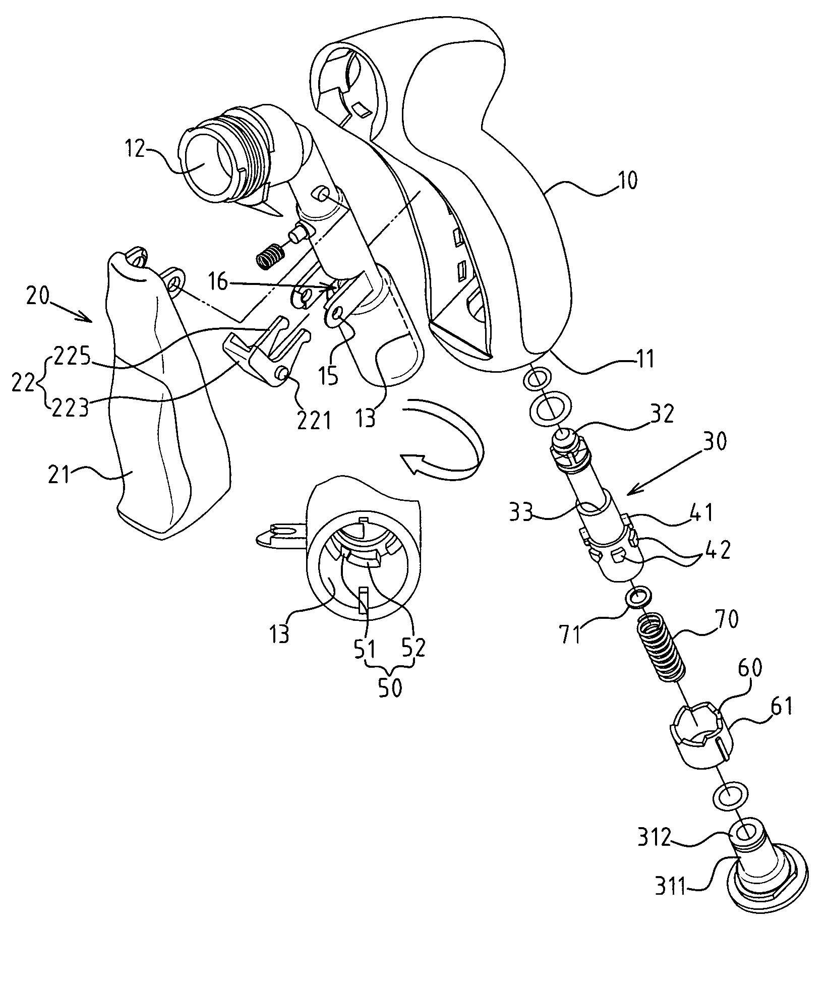
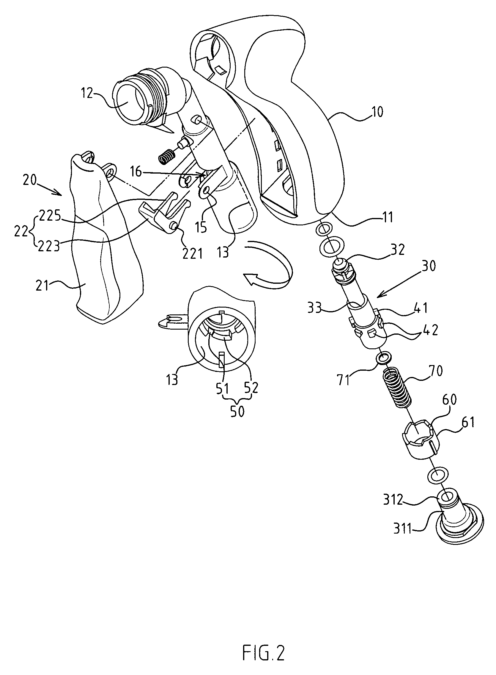
[0010]The water flow control structure of the present invention primarily consists of the design of the movable control tube 30, stepwise positioning unit 50, oblique guide 60, and resilient component 70. When the control tube 30 is moved by the control component 20, it is turned by the movement of the oblique guide 60 and stepwise positioning unit 50. The first guide 41 of the control tube 30 faces a different position 51, 51B, 51C of the stepwise positioning unit 50 to control the space between the stopper head 32 of the control tube 30 and the water control outlet 14 of the water holder 13 so as to control the water flow. The entire control structure is hidden inside the water gun, which solves the disadvantages of the conventional structures, such as avoiding damage from outside forces, reducing the damage rate, avoiding contact with mud and sand, and keeping the movement functioning normally.
[0011]The water flow control of the water gun of the present invention uses the repeat movement of the control component 20 to switch the water flow control, which is convenient and practical to use.

Problems solved by technology

However, when people use the water gun and when the distance of the target is different one from another, the need to adjust the water flow arises.
It is a challenge to maintain a certain amount of the water flow, and the hand often becomes sore from holding the trigger for a long period of time.
Thus, the water gun becomes inconvenient when used for a long time.
The structure that is used to adjust the water flow, such as the assisting button and gear, is placed on the external side of the water gun; therefore, the damage rate is higher during actual use.
Moreover, because the water gun is often used for garden irrigation or cleaning, the water gun is soiled with mud and sand.
The mud and sand easily gets inside the gear and fills the empty part of the structure, which affects the normal positioning effect of the gear.

Method used


Image

  • Water flow control structure of a water gun
  • Water flow control structure of a water gun
  • Water flow control structure of a water gun

Examples


Embodiment Construction

[0023]The features and the advantages of the present invention will be more readily understood upon a thoughtful deliberation of the following detailed description of a preferred embodiment of the present invention with reference to the accompanying drawing.

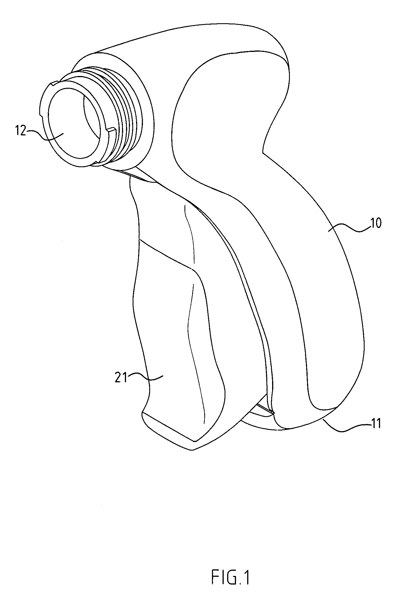
[0024]As shown in FIGS. 1, 2, 3, 4, there is a water flow control structure embodied in the present invention. This embodiment is used for description only. The scope of the invention is determined by the claims and is not restricted by this description of the structure when applying for the patent. The water flow control structure is placed on the predetermined part of the water gun to control the on and off features and the amount of the water flow.

[0025]A water gun 10 includes a water inlet 11, a water outlet 12, a water holder 13 between the water inlet 11 and the water outlet 12, and a control component 20 placed on a predetermined part of the water gun 10.

[0026]The flow control structure includes a control tube 30, which is...


PUM


Abstract

The water flow control structure of a water gun includes a movable control tube, stepwise positioning unit, oblique guide and resilient component. When the control tube is moved by the control component, it is turned by the oblique guide and stepwise positioning unit. Each time the first guide of the control tube coordinates with the position of the stepwise positioning unit, it makes the space between the stopper head of the control tube and the water control outlet of the water holder close or open in different degrees to control water flow. The entire control structure is hidden inside the water gun. The repeated movements of the control component can switch the water flow mode, which is convenient and practical.

Description

RELATED U.S. APPLICATIONS[0001]Not applicable.STATEMENT REGARDING FEDERALLY SPONSORED RESEARCH OR DEVELOPMENT[0002]Not applicable.REFERENCE TO MICROFICHE APPENDIX[0003]Not applicable.FIELD OF THE INVENTION[0004]The present invention relates generally to a water flow control structure of a water gun, and more particularly to a device with a rotating cylinder with an oblique guide and stepwise positioning unit to adjust the water flow and its on and off feature.BACKGROUND OF THE INVENTION[0005]When using the conventional water gun, the water gun usually controls the on and off status of water flow by a predetermined pressing part or trigger. However, when people use the water gun and when the distance of the target is different one from another, the need to adjust the water flow arises. The conventional water gun has only two modes, on and off; therefore, water flow control is achieved by pressing the trigger. It is a challenge to maintain a certain amount of the water flow, and the h...

Claims


Application Information

Patent Timeline
Patent Type & Authority Patents(United States)
IPC IPC(8): F16K31/60
CPCB05B1/3013B05B1/3066B05B12/002
Inventor WANG, HSIN-FA
Owner WANG HSIN FA
Why Eureka
Eureka Blog
Learn More