Connector and connector system

a technology of connectors and connectors, applied in the direction of fixed connections, coupling device connections, coupling protective earth/shielding arrangements, etc., can solve the problems of the external size of the connector directly affecting the mounting space of the circuit board, and the difficulty of forming a complementary fitting portion, so as to achieve the effect of avoiding the increase in the depth of the connector, reducing the external size of the connector, and increasing the height of the connector

Inactive Publication Date: 2008-05-27
3M INNOVATIVE PROPERTIES CO
View PDF24 Cites 43 Cited by
  • Summary
  • Abstract
  • Description
  • Claims
  • Application Information

AI Technical Summary

Benefits of technology

[0027]According to the invention of claim 1, the conductor-connecting sections of the terminal elements and the contact sections are arranged in alignment in a direction intersecting the connector fitting direction. Therefore, the structure for connecting the conductor-connecting sections of the terminal elements to the conductors of the wires can be arranged being suitably deviated in a direction to intersect the connector fitting direction relative to the fitting portion of the body. As a result, an increase in the height of the connector (external size in the connector fitting direction) can be effectively avoided. The connector employs a wire connection structure of a very simple conductor abut type in which the conductor-connecting sections of the terminal elements are pressed onto the conductors of the wires so as to be connected thereto. Therefore, the above characteristic arrangement of the terminal elements does not at all affect the connection between the terminal elements and the wires. According to the present invention, therefore, the external size (particularly, height) of the connector can be decreased as much as possible without impairing the stability and reliability of connection between the terminal elements and the wire conductors.
[0028]According to the invention of claim 2, the connector fitting direction is nearly at right angles with the direction in which the wires extend on the body. Basically, therefore, it is allowed to avoid an increase in the depth of the connector (external size along the direction in which the wires extend). Besides, the wires are arranged on the back side of the fitting portion as seen in the connector fitting direction. Therefore, an increase in the depth of the connector is effectively avoided even when the connection structure between the conductor-connecting sections of the terminal elements and the conductors of the wires is arranged being deviated in a direction to intersect the connector fitting direction relative to the fitting portion.
[0029]According to the invention of claim 3, the body is divided into the first support member and the second support member, and the conductors of the wires to be connected are arranged in advance between the conductor-connecting sections of the terminal elements supported by the first support member and the bearing surfaces of the second support member. During the work for connecting the wires, therefore, there does not occur such a situation that the wire conductors are rubbed against the metal piece with pressure, and there is no probability that the wire conductors are damaged.
[0030]According to the invention of claim 4, the abutting member is simply assembled with the body such that the pressing surface of the abutting member presses the conductor-connecting sections of the terminal elements against the corresponding bearing surfaces. Therefore, a required contacting pressure is easily maintained between the terminal elements and the wire conductors.
[0031]According to the invention of claim 5, the first shield member comes into conductive contact with the second shield member when the connector is assembled substantially surrounding the conductor-connecting sections of the terminal elements and the wire conductors connected thereto in a non-contacting manner. By connecting the first and second shield members to the ground potential, therefore, a shielding structure is established for the signal transmission path in the connector, and the connector exhibits improved high-speed transmission characteristics.
[0032]According to the invention of claim 6, a shielding structure of a high level is established by using the first and second shield member of a potential equal to that of the shieldings of coaxial cables so will not to impair excellent high-speed transmission characteristics possessed by the coaxial cables.

Problems solved by technology

During the work for connecting the electric wires, therefore, the conductors of the wires are rubbed against the metal pieces with pressure, and the conductors may be damaged.
In the field of connectors for connecting the cables and the substrate, in particular, the external size of the connector directly affects the mounting space of the circuit board.
In the connectors, in general, it is becoming difficult to form a complementary fitting portion that is capable of maintaining a state in which the corresponding terminal elements are in contact maintaining stability in a pair of connectors that are connected to each other due to a decrease in the external size as described above.

Method used


Image

  • Connector and connector system
  • Connector and connector system
  • Connector and connector system

Examples


Embodiment Construction

[0053]An embodiment of the invention will now be described in detail with reference to the accompanying drawings. In the drawings, the corresponding constituent elements are denoted by the same reference numerals.

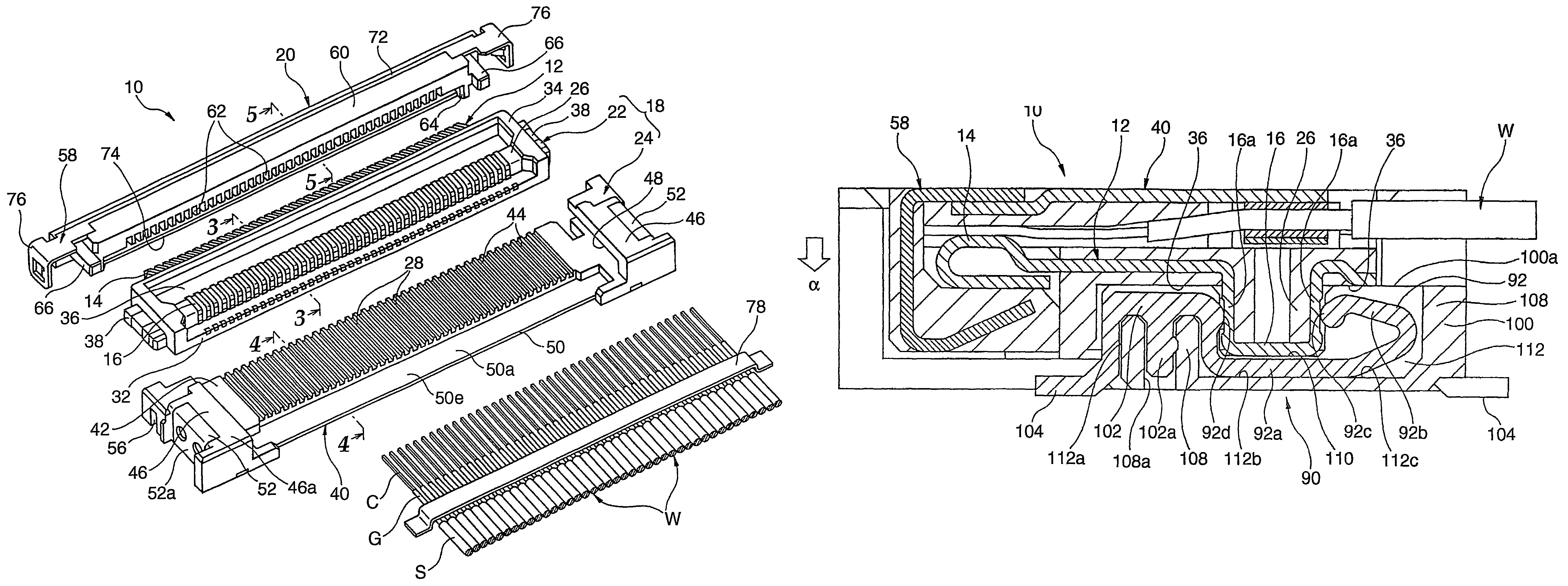
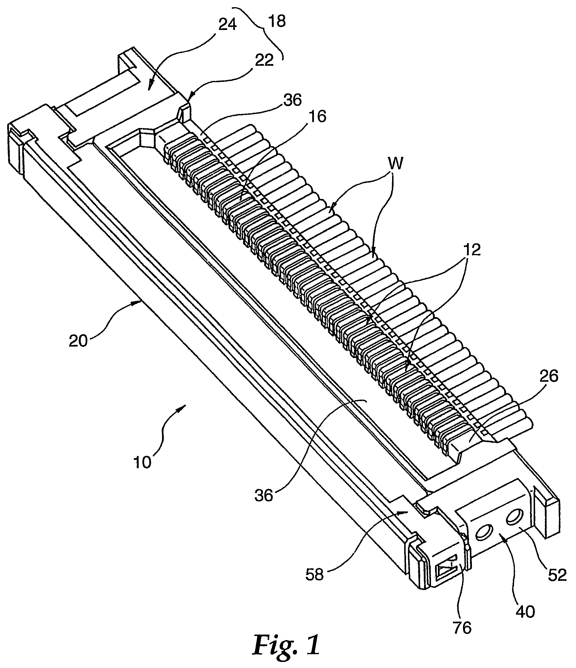
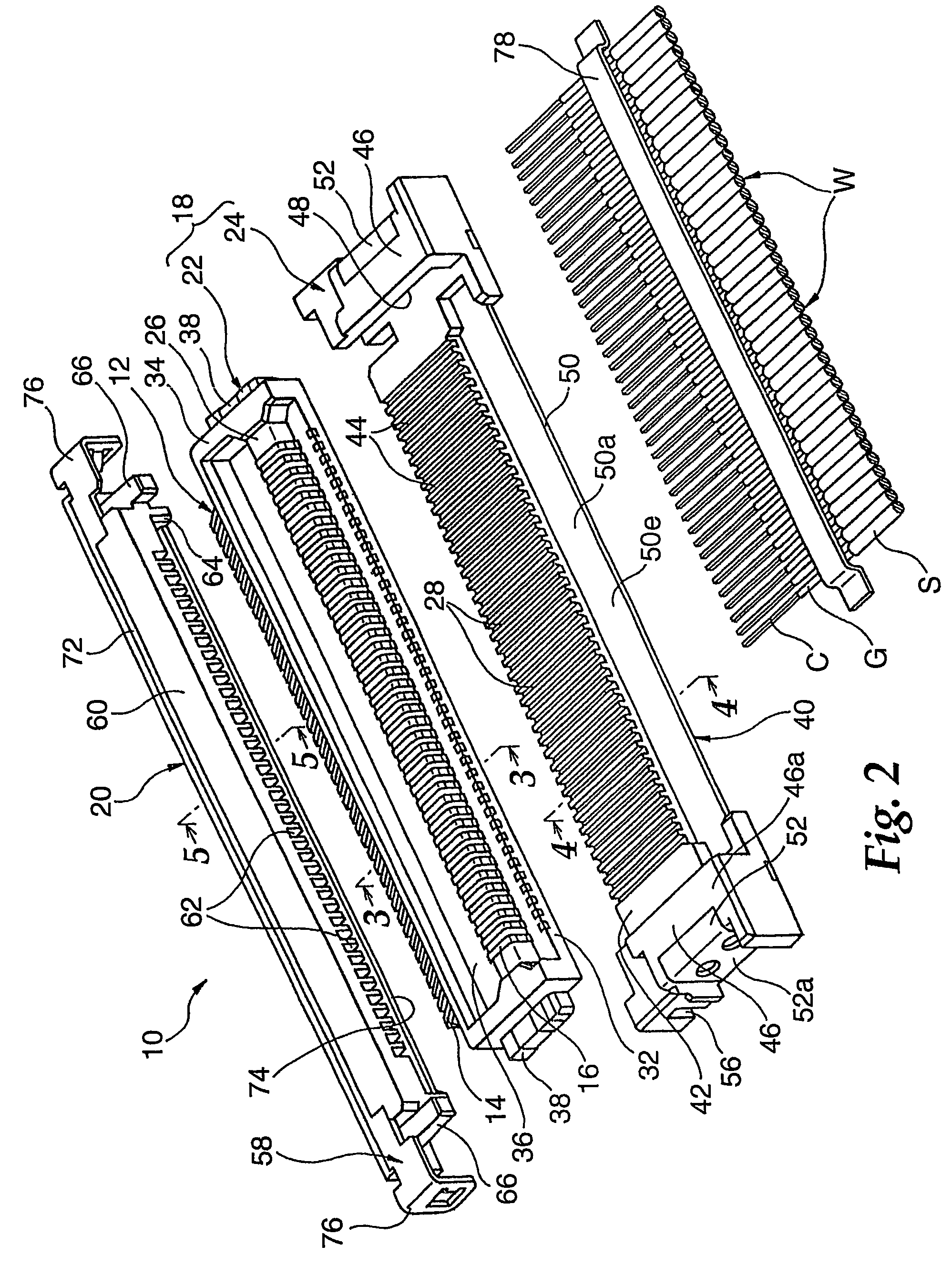
[0054]FIG. 1 is a perspective view illustrating a state where a connector 10 is assembled according to an embodiment of the present invention, FIG. 2 is a perspective view illustrating the connector 10 in a disassembled manner, and FIGS. 3 to 5 are sectional views illustrating principal constituent elements of the connector 10. The connector 10 has a wire connection structure of a conductor abut type in which a conductor C exposed by removing a sheath S at an end of a wire W over a required length is connected being abut to a conductor-connecting section 14 of a terminal element 12. The connector 10 can be advantageously used for connecting a multi-core flat coaxial cable to a circuit board. In this case, the other connector (referred to as counterpart connector in this spe...


PUM


Abstract

A connector is provided with a terminal element including a conductor-connecting section connectable to a conductor of an electric wire and a contact section capable conductively contacting with a corresponding terminal element of a counterpart connector, an electrically insulating body for supporting the terminal element while exposing the conductor-connecting section and the contact section, and an abutting member assembled with the body and bringing the wire conductor into abutment with the conductor-connecting section under pressure. The body includes a fining portion capable of fining with a counterpart connector while positioning the contact section with respect to the corresponding terminal element. The conductor-connecting section and the contact section are arranged to be aligned with each other generally orthogonal to a connector fitting direction defined by the fitting portion.

Description

CROSS REFERENCE TO RELATED APPLICATIONS[0001]This application is a national stage filing under 35 U.S.C. 371 of PCT / US2004 / 031258, filed Sep. 22, 2004, which claims priority to Japanese Application No. 2003-360695, filed Oct. 21, 2003.TECHNICAL FIELD[0002]The present invention relates to a connector having a wire connection structure of a conductor abutting type which brings the conductor-connecting sections of terminal elements and the conductors of wires into contact with each other with pressure. The invention further relates to a connector for a circuit board that can be connected to a connector having a wire connection structure of the conductor abutting type. The invention further relates to a connector system for connecting cables to a substrate.BACKGROUND ART[0003]As structures for mutually connecting terminal elements of connectors and wire conductors to each other, there have been known a structure in which conductor-connecting sections of terminal elements are plastically...

Claims


Application Information

Patent Timeline
Patent Type & Authority Patents(United States)
IPC IPC(8): H01R12/24H01R9/05H01R12/59H01R12/62H01R12/71H01R12/79H01R13/658H01R24/00
CPCH01R12/592H01R12/598H01R9/05H01R12/716H01R12/79H01R23/6873H01R13/658
Inventor MATSUOKA, HIROYUKI
Owner 3M INNOVATIVE PROPERTIES CO
Why Eureka
Try Eureka