Method and apparatus for controlling in thermal printer

a thermal printer and control method technology, applied in printing, other printing apparatus, etc., can solve the problems of high printing cost per page, high final product cost, complicated structure of printing equipment,

Inactive Publication Date: 2008-05-27
S PRINTING SOLUTION CO LTD
View PDF23 Cites 22 Cited by
  • Summary
  • Abstract
  • Description
  • Claims
  • Application Information

AI Technical Summary

Benefits of technology

[0012]The present invention provides a method and apparatus for controlling printing which increases the temperature of a printhead in a process of preparing for printing.

Problems solved by technology

The devices using the ink ribbon require an additional apparatus for driving the ink ribbon so that the structure thereof is complicated and a final product is expensive.
Also, since the ink ribbon is provided as a consumable product, it needs to be continuously replaced, such that resulting printing costs per page are high.
In particular, when the printer is in a ready mode or prints the first page, if the temperature of the TPH is lower than the minimum target temperature, the color of the ink layer of the thermal reactive paper is insufficiently displayed.

Method used


Image

  • Method and apparatus for controlling in thermal printer
  • Method and apparatus for controlling in thermal printer
  • Method and apparatus for controlling in thermal printer

Examples


Embodiment Construction

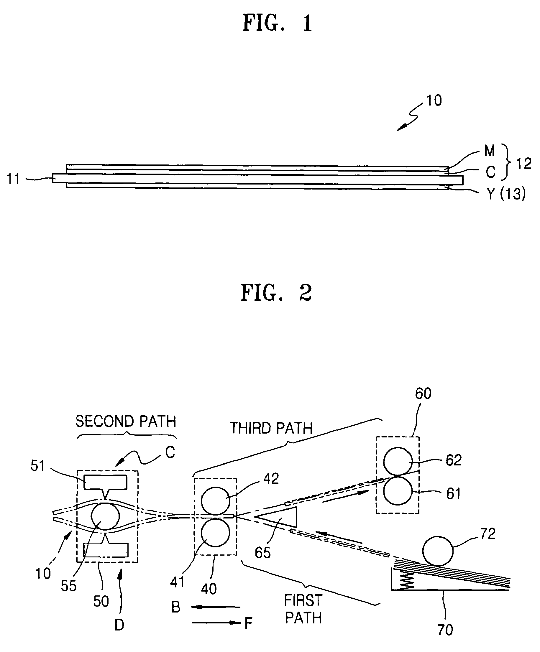
[0031]FIG. 2 is a view illustrating a thermal printer using a method for controlling printing according to an embodiment of the present invention. Referring to FIG. 2, a thermal printer comprises at least first, second and third paths along which a thermal reactive paper 10 is transferred. The first path is a paper supply path along which the thermal reactive paper 10 is transferred to the second path. Along the second path, the thermal reactive paper 10 is fed backward in a direction B for preparation of printing on the thermal reactive paper 10, and forward in direction F for printing. The third path is a path where the thermal reactive paper 10 being printed is located, and is also a path along which the thermal reactive paper 10 having only a first surface printed returns to the second path and where the thermal reactive paper 10 having the first and second surfaces printed is finally discharged.

[0032]A paper guide 65 is provided between the first and third paths. The paper guid...


PUM


Abstract

A system and method is provided for controlling printing in a thermal printer which includes measuring a temperature of a thermal printhead (TPH), heating the TPH by applying a TPH driving strobe pulse when the temperature of the TPH is lower than a first set temperature, and printing on a thermal reactive paper when the temperature of the TPH is equal to or greater than the first set temperature.

Description

CROSS-REFERENCE TO RELATED APPLICATIONS[0001]This application claims the benefit under 35 U.S.C. §119(a) of Korean Patent Application No. 10-2004-0095061, filed in the Korean Intellectual Property Office on Nov. 19, 2004, the entire disclosure of which is incorporated herein by reference.BACKGROUND OF THE INVENTION[0002]1. Field of the Invention[0003]The present invention relates to a method and apparatus for controlling printing in a thermal printer. More specifically, the present invention relates to a method and apparatus for controlling printing in a thermal printer while maintaining a temperature of a thermal printhead (TPH) for applying a predetermined heat to a double-sided thermal reactive paper.[0004]2. Description of the Related Art[0005]Thermal printers include a number of devices which typically use print paper (hereinafter, referred to as “thermal reactive paper”) which displays a predetermined color by reacting to heat, and include a number of devices which typically u...

Claims


Application Information

Patent Timeline
Patent Type & Authority Patents(United States)
IPC IPC(8): B41J2/38
CPCB41J2/365B41J29/377B41J29/393B41J11/36
Inventor JO, GYEONG-HUNCHUNG, JIN-TAE
Owner S PRINTING SOLUTION CO LTD
Why Eureka
Try Eureka