Transmission method and apparatus for optical fiber television network

a technology of optical fiber and television network, applied in the field of fiber optic television network, can solve the problems of inability to bring optical fiber directly into the home, limited bandwidth of cable television network, and inability to meet the needs of the home, so as to achieve the effect of facilitating buffering and facilitating transmission

Inactive Publication Date: 2008-05-27
LUCENT TECH INC
View PDF8 Cites 6 Cited by
  • Summary
  • Abstract
  • Description
  • Claims
  • Application Information

AI Technical Summary

Benefits of technology

[0017]In one embodiment of the invention, the information that is placed in the buffers is the instantaneous data being transmitted on that channel at the time of the buffering. Accordingly, every time a user changes channels and views the buffered data, he is watching data from the recent past. However, in alternative embodiments of the invention, the data may be buffered in advance. In particular, the vast majority of television programming is prerecorded and can be transmitted for buffering ahead of time. In this type of system, the buffer should be made large enough to hold a plurality of samples for each channel. When a user changes to a given channel, the sample most closely corresponding in time to the present time is read out to the television. In this type of system, in which the buffer information for channels is transmitted ahead of time, the buffers can be filled more effectively since buffering can occur while no television program is being watched, thus, providing even greater transmission bandwidth for buffering. Further, the samples to be transmitted for storage can be selected so as to transmit program samples that are highly indicative of the program. For instance, samples can be selected so as to avoid samples of commercial breaks.

Problems solved by technology

Since transmission antennas are earth based, and transmission powers are limited by law, adequate reception is commonly limited to less than 100 miles from the transmitting antenna.
The bandwidth of cable television networks is limited by the physical characteristics of the coaxial cable.
Fiber optic television networks had been explored earlier, but most of that work, including bringing optical fiber directly into the home, had been abandoned.
Such systems were generally not well received because the equipment needed to transmit / receive with many different wavelengths on a single fiber tended to be expensive and difficult to operate in a stable manner.
However, with the expected increasing prevalence of digital data being transmitted to residences, fiber optic transmission means are again coming under increased scrutiny.
However, achieving such bandwidth is extremely expensive and, therefore, not practical for bringing television signals into individual homes.
With current technology, digital communication over a low cost optical fiber simply does not provide sufficient bandwidth to transmit 100 or even 50 simultaneous channels of television programming.

Method used


Image

  • Transmission method and apparatus for optical fiber television network
  • Transmission method and apparatus for optical fiber television network
  • Transmission method and apparatus for optical fiber television network

Examples


Embodiment Construction

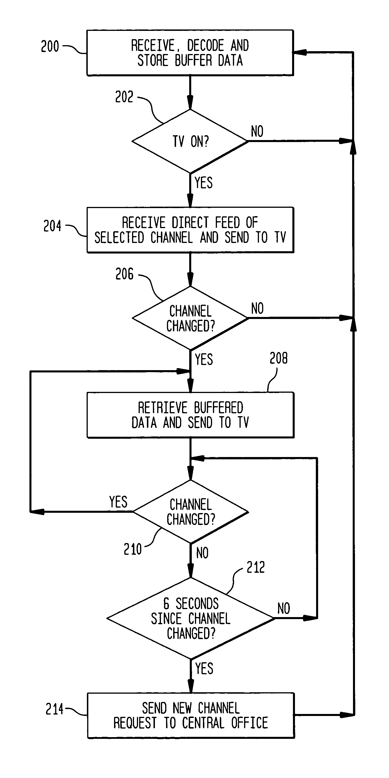
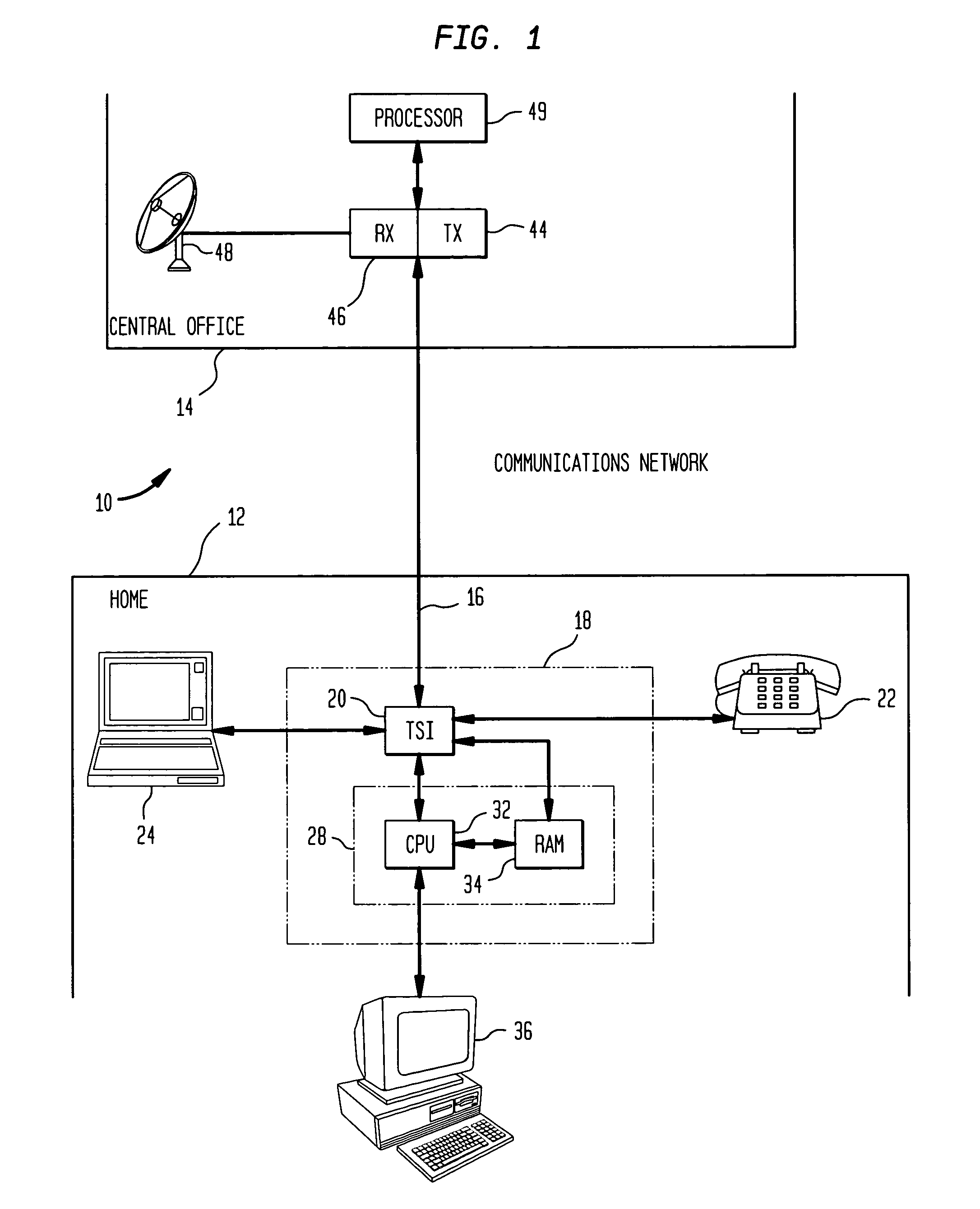
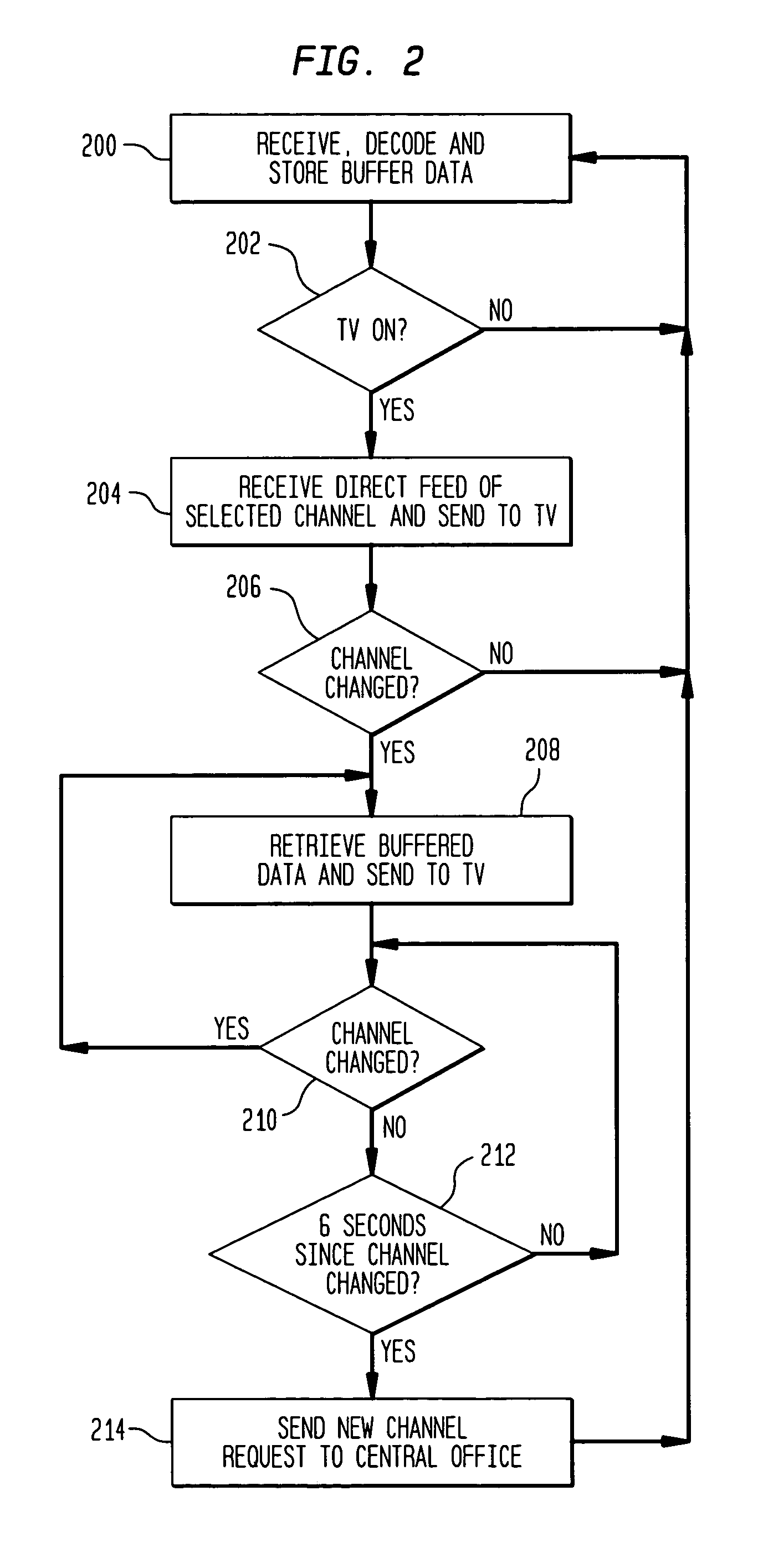
[0021]FIG. 1 is a block diagram of a fiber optic communications network for providing television, telephone, and Internet services to a household. Because the invention can be adequately illustrated and described in connection with the communication between a single household and a central service office, FIG. 1 illustrates only a single household node 12 in the network. However, it should be understood that a typical communications network comprises a central office 14 and a plurality of household nodes 12. Further, the present invention primarily relates to the provision of multiple channels of television service over an optical fiber having less available bandwidth than is needed to transmit the entire multiple channel television information. Accordingly, for ease of illustration and explanation, the connection between the central office and the home is shown in the illustration as a single optical fiber. However, it will be understood by those skilled in the art that the fiber o...


PUM


Abstract

A method and apparatus by which television service is provided to the home via a two-way fiber optic link. The television set transmits to the central office the channel or channels being watched. Information from all other available channels which are not being watched is constantly being buffered and up-dated at the television set location. The buffering can be performed using a bandwidth available on the optical fiber that is not being used for the one or two television channels being watched or for other uses. When a user changes channels, he is shown the buffered data for a limited time. When the buffer runs out, the home office is notified of the channel change and commences transmitting the newly selected channel in full.

Description

FIELD OF INVENTION[0001]The invention pertains to the provision of rapid access to multiple channels in a limited bandwidth environment in which all channels cannot be transmitted simultaneously. More particularly, the invention pertains to fiber optic television networks.BACKGROUND OF THE INVENTION[0002]Presently, most television viewers receive their television signals through one of three primary media. The oldest method is through radio frequency broadcast of analog signals from earth based transmitting antennae.[0003]In the United States, for example, each television channel is provided 6 MHz of bandwidth in the radio frequency range. The radio frequency bandwidth provided for television in the United States offers 12 channels (channels 2-13) in the very high frequency (VHF) range and an additional approximately 71 channels in the ultra high frequency (UHF) range.[0004]Radio frequency broadcast television is an analog system. That is, the television signals are broadcast in ana...

Claims


Application Information

Patent Timeline
Patent Type & Authority Patents(United States)
IPC IPC(8): H04N5/445G06F13/00H04N7/173G06F3/00
CPCH04N7/17318H04N21/4331H04N21/4384H04N21/44222H04N21/44224
Inventor STAYT, JR., JOHN W.
Owner LUCENT TECH INC
Why Eureka
Try Eureka