

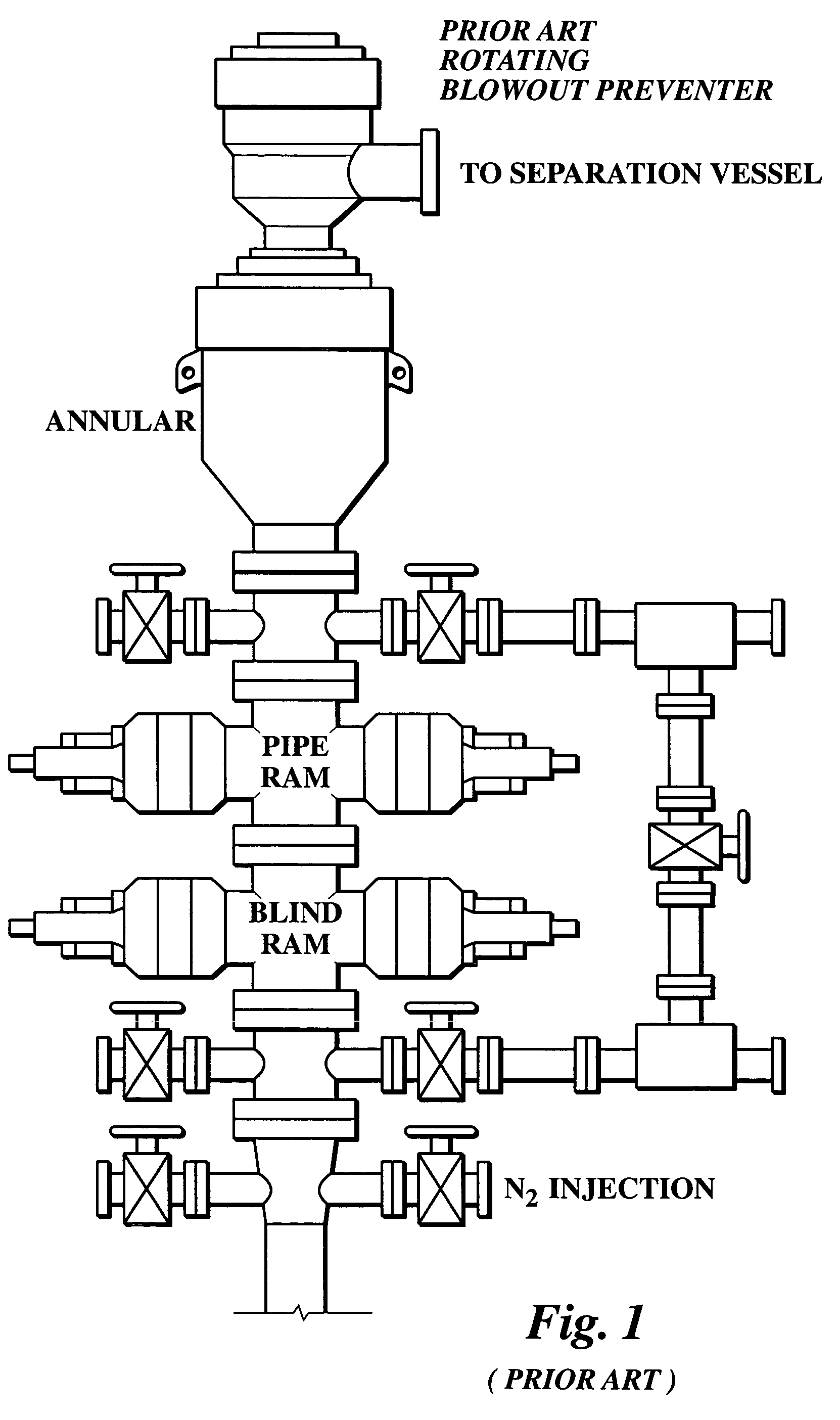
Rotating pressure control head
a control head and rotating pressure technology, applied in the direction of couplings, wellbore/well accessories, sealing/packing, etc., can solve the problems of high probability of hydrocarbons being ignited, damage to equipment that maintains, and potential blowout, so as to reduce harmonic vibration, increase well bore pressure, and engage quickly
- Summary
- Abstract
- Description
- Claims
- Application Information
AI Technical Summary
Benefits of technology
Problems solved by technology
Method used
Image

Examples
Embodiment Construction
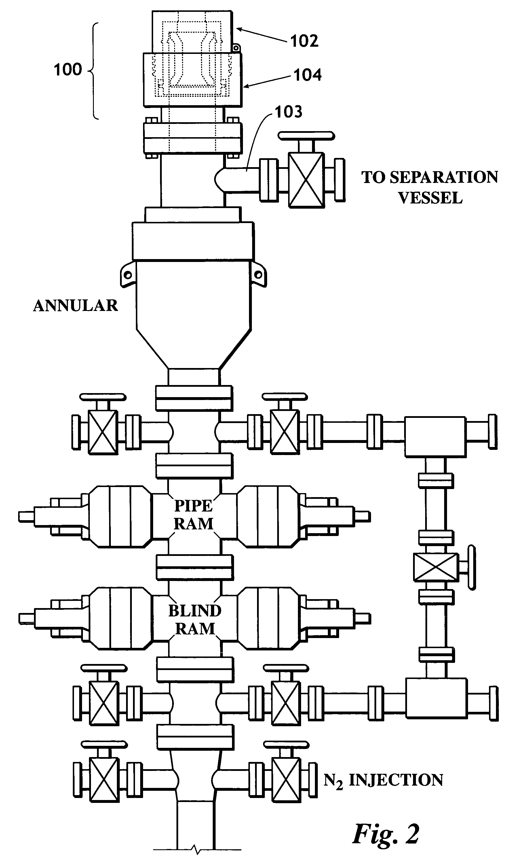
[0034]FIG. 2 is an illustration of a blowout control stack employing the present invention, the Rotating Pressure Control Head (RPCH) 100, in place of the prior art rotating BOP shown in FIG. 1. RPCH 100 is affixed to a stack including a prior art annular ram, a prior art blind ram, a prior art pipe ram, and prior art gas injection. Persons of ordinary skill in the art will also appreciate the fact that RPCH 100 may replace not only the prior art rotating BOP, but the annular ram, the blind ram, and optionally the pipe ram when the well bore pressure does not exceed 1,500 psi. Utilization of the present invention to replace the prior art rotating BOP, the annular ram, the blind ram, and the pipe ram significantly reduces the height of the BOP stack. RPCH 100 has upper body 102 and lower body 104. Moreover, as discussed further below (see FIG. 19 through FIG. 21), lower body 104 may be modified to include outlet 103 for connection to a separation vessel.
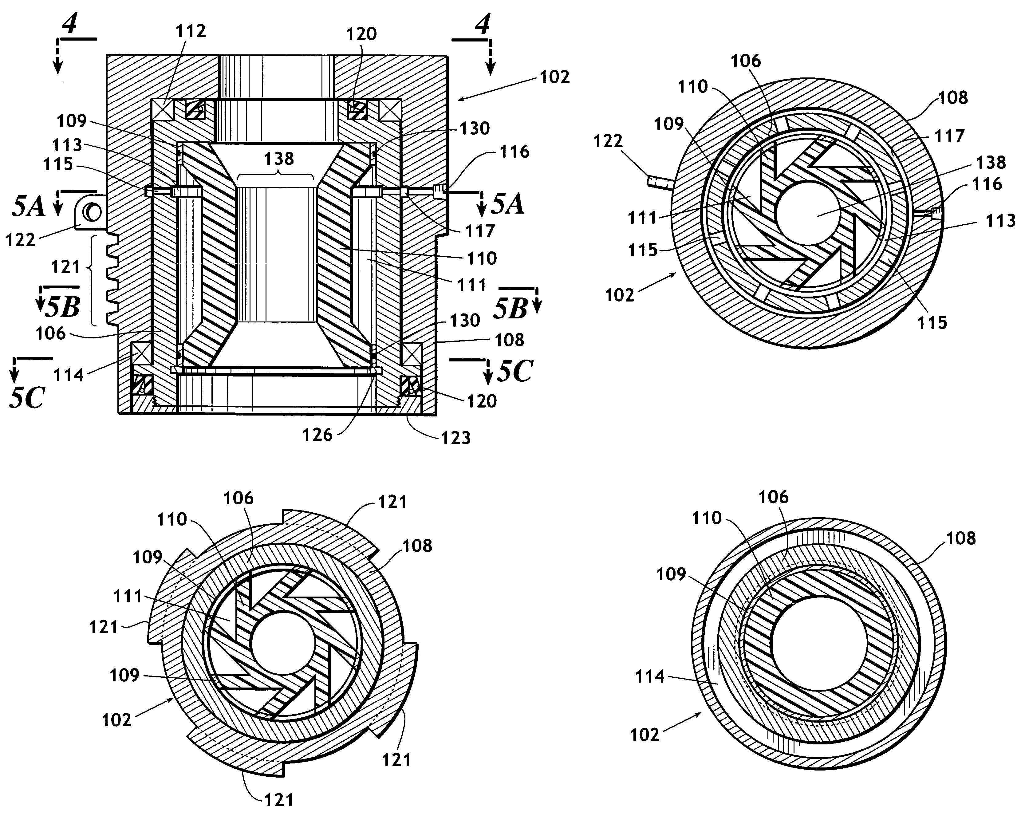
[0035]FIG. 3 is a cross-sectio...
PUM
 Abstract
Description
Claims
Application Information