Tire uniformity machine grinding assembly

a technology of uniformity machine and grinding assembly, which is applied in the direction of grinding head, application, manufacturing tools, etc., can solve the problems of rotating the pivotal arm, affecting the uniformity of the tire, and causing the rotation of the pivotal arm to not aim the grindstone directly at the center of the tire,

Active Publication Date: 2008-06-03
AKRON SPECIAL MACHINERY
View PDF10 Cites 15 Cited by
  • Summary
  • Abstract
  • Description
  • Claims
  • Application Information

AI Technical Summary

Problems solved by technology

Because the motor needed to drive the belts or chains, and the gear box arrangement is bulky, the housing of the motor projects to such an extent that the confines of the tire uniformity machine prevent the grindstone from being actuated in a linear fashion inward and outward with respect to the tire.
Rotation of the pivotal arm, however, may not aim the grindstone directly at the center of the tire.
Due to machining tolerances, each link is a potential source of error.
When multiple links are used, such errors are compounded making it more significant in terms of accurately positioning the grindstone to remove material from the tire.
In fact, when dual grindstones, a leading and a trailing grindstone, are provided, use of such linkages virtually eliminates the ability of the grinder to have both grindstones strike the tire simultaneously, and, in some cases, may cause one of the grindstones to be out of contact with the tire.
However, when errors occur using the linkages, the trailing grindstone is precluded from performing its corrective function.
As discussed above, the pivoting arm supporting single or dual grindstones can be a source of inaccuracy in positioning the grindstone or grindstones relative to the tire.
Moreover, pivotably supporting the grindstone relative to the pivoting arm so that the grindstone or grindstones can be pivoted to account for rotation of the pivoting arm introduces additional inaccuracies.

Method used


Image

  • Tire uniformity machine grinding assembly
  • Tire uniformity machine grinding assembly
  • Tire uniformity machine grinding assembly

Examples


Embodiment Construction

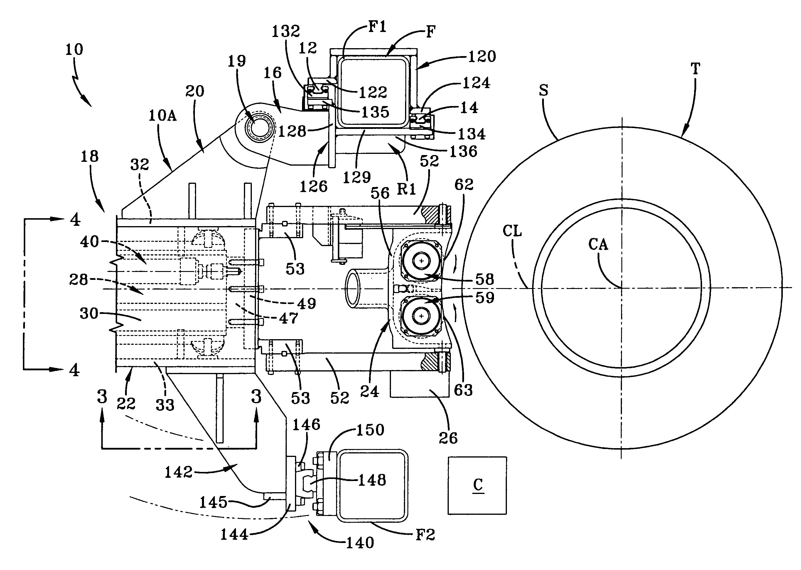
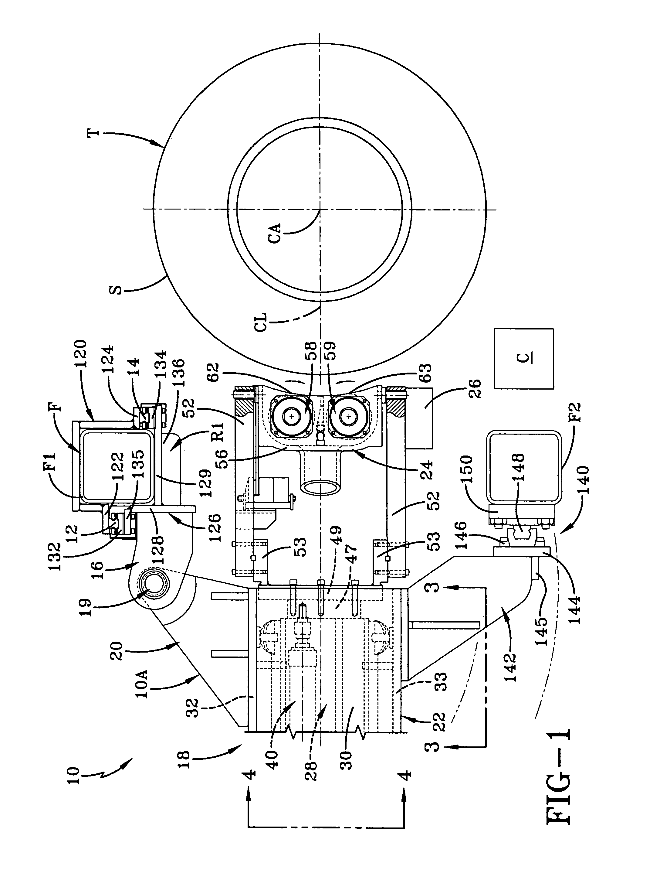
[0024]A grinder assembly according to the present invention is generally referred to by the numeral 10 in the accompanying drawing figures. The grinder assembly 10 removes material from a tire T. The grinding assembly 10 may be used in association with tire machines in a lathe-like manner to remove material as the tire T rotates about a central axis CA. Optionally, grinding assembly 10 may be used in connection with a tire uniformity machine (not shown). In this example, uniformity testing and grinding could be performed at a single location. Such machines are well-known and will only be generally described herein.

[0025]The grinder assembly 10 is suitably supported proximate to tire T to effect such contact, for example, by a frame F having frame members F1 and F2. The frame F may be an independent support, or be a part of the tire machine frame. As shown in FIG. 5, the grinder assembly 10 may include an upper section 10A and a lower section 10B. In the example shown, the upper sect...


PUM

PropertyMeasurementUnit
speedsaaaaaaaaaa
shapeaaaaaaaaaa
surface qualitiesaaaaaaaaaa

Abstract

A grinder assembly (10) contacts a tire (T) supported by a frame (F) relative to the tire (T). The grinder assembly (10) includes at least one section, and a vertical repositioning system (118) supporting the at least one section. The vertical repositioning system (118) enables the at least one section to be vertically repositioned relative to the tire (T). The at least one section includes a grinding head (24), a radial positioning system (18) supporting the grinding head (24) for radial movement with respect to the tire (T), and a tilt adjuster (90) provided adjacent the grinding head (24) to provide for pivotal movement thereof. The vertical repositioning system (118) includes at least one rail extending along the frame (F), and a rail carriage supporting the at least one section on the at least one rail, the rail carriage being vertically repositionable along the at least one rail.

Description

RELATED APPLICATIONS[0001]This application claims the benefit of U.S. Provisional Application No. 60 / 548,495 filed on Feb. 27, 2004.TECHNICAL FIELD[0002]In general, the present invention relates to a tire uniformity machine. More particularly, the present invention relates to a tire uniformity machine employing a grinding assembly having an upper section and a lower section including grinding heads capable of independent vertical, radial, and pivotal movement with respect to a tire mounted on the tire uniformity machine.BACKGROUND OF THE INVENTION[0003]In tire uniformity machines, a tire is tested by rotating it at various speeds to ensure that the tire has been constructed to perform within quality control standards. During this testing process, the tire is rotated, and the tire uniformity machine examines the tire's integrity, shape, and surface qualities to a high degree of accuracy. At times, during examination, the tire uniformity machine detects irregularities in the tire. Any...

Claims


Application Information

Patent Timeline
Patent Type & Authority Patents(United States)
IPC IPC(8): B24B49/00B24B1/00B24B5/00B24B5/18B24B5/36B24B41/00
CPCB24B5/366B24B41/002B24B49/00B29D2030/541B29D2030/546Y10S451/92
Inventor POLING, SR., DAVIDDELMORO, RICHARDKRAUSE, DAVID
Owner AKRON SPECIAL MACHINERY
Why Eureka
Try Eureka