
Multi-lumen catheter with attachable hub

a multi-lumen catheter and hub technology, applied in the field of medical instruments, can solve the problems of poor dialysis treatment effect, lack of accuracy of catheter tip placement, and lack of double-lumen catheters

Inactive Publication Date: 2008-06-03
TELEFLEX LIFE SCI LTD
View PDF96 Cites 129 Cited by
  • Summary
  • Abstract
  • Description
  • Claims
  • Application Information

AI Technical Summary

Benefits of technology

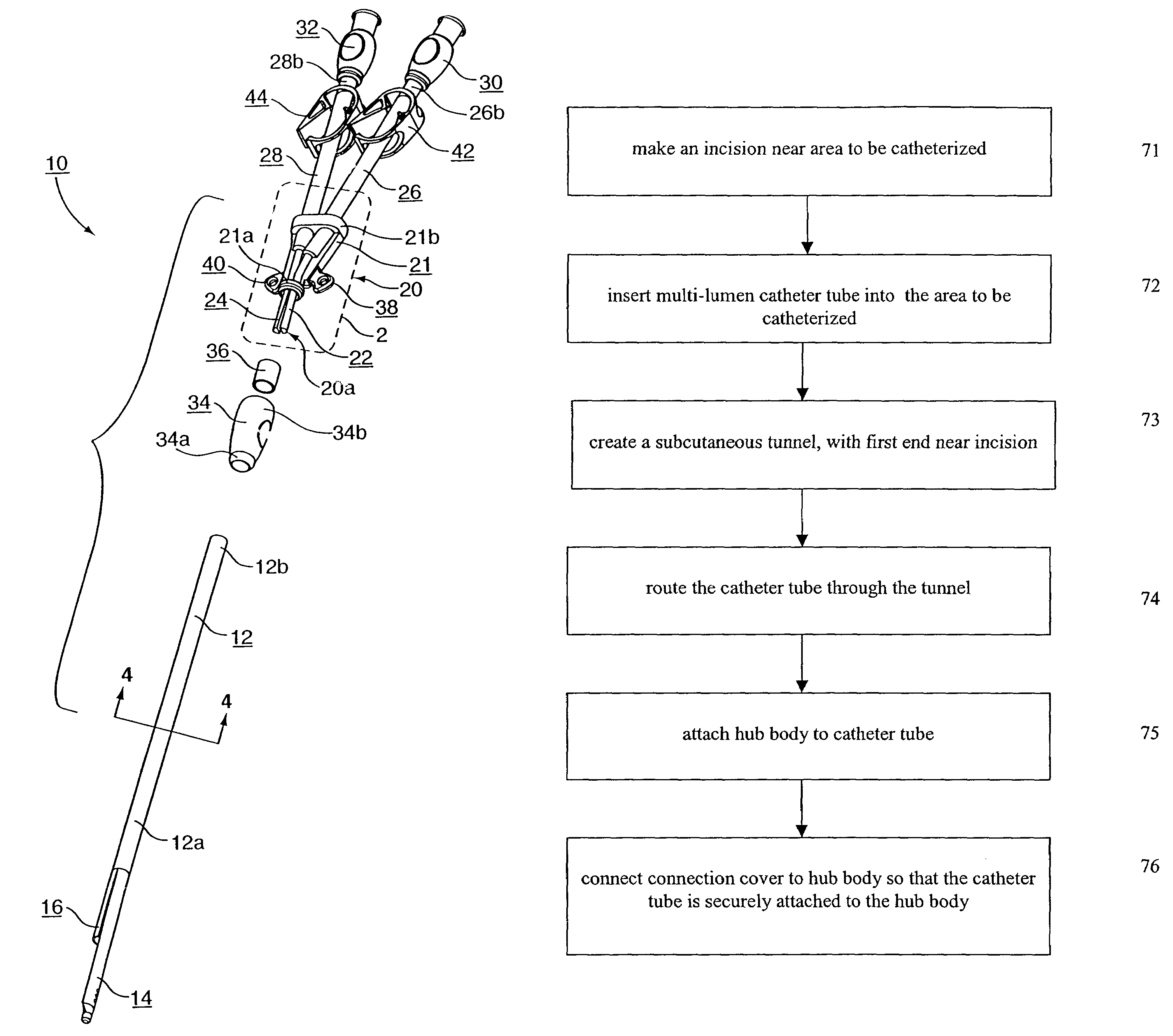
The present invention is a method for inserting a multi-lumen catheter assembly into an area to be catheterized. The catheter assembly includes a multi-lumen catheter tube, an attachable hub assembly, and a compression sleeve. The hub assembly has two cannulae with indicators associated with them. The method involves making an incision near the area to be catheterized, routing the catheter tube through a subcutaneous tunnel, and attaching the hub assembly to the catheter tube. The technical effect of this invention is a secure and reliable attachment of the catheter tube to the hub assembly, allowing for fluid communication between the cannulae and the lumen of the catheter tube.

Problems solved by technology

Both types, however, present certain deficiencies.
While double lumen catheters (e.g., U.S. Pat. No. 4,895,561) allow for a single venous insertion of the catheter into the desired vein, double lumen catheters typically do not provide for accuracy of catheter tip placement.
Non-optimal tip position may significantly lower flow values, resulting in less effective dialysis treatment.
The initial estimate and subsequent forward tunneling may result in less than optimal tip placement.
Deficiencies, however, exist in this method of catheterization as well.
One problem associated with this method is that this method requires two separate venous insertions, namely, two tunnels and two of each accessory instrument used for the procedure.

Method used


Image

  • Multi-lumen catheter with attachable hub
  • Multi-lumen catheter with attachable hub
  • Multi-lumen catheter with attachable hub

Examples


Embodiment Construction

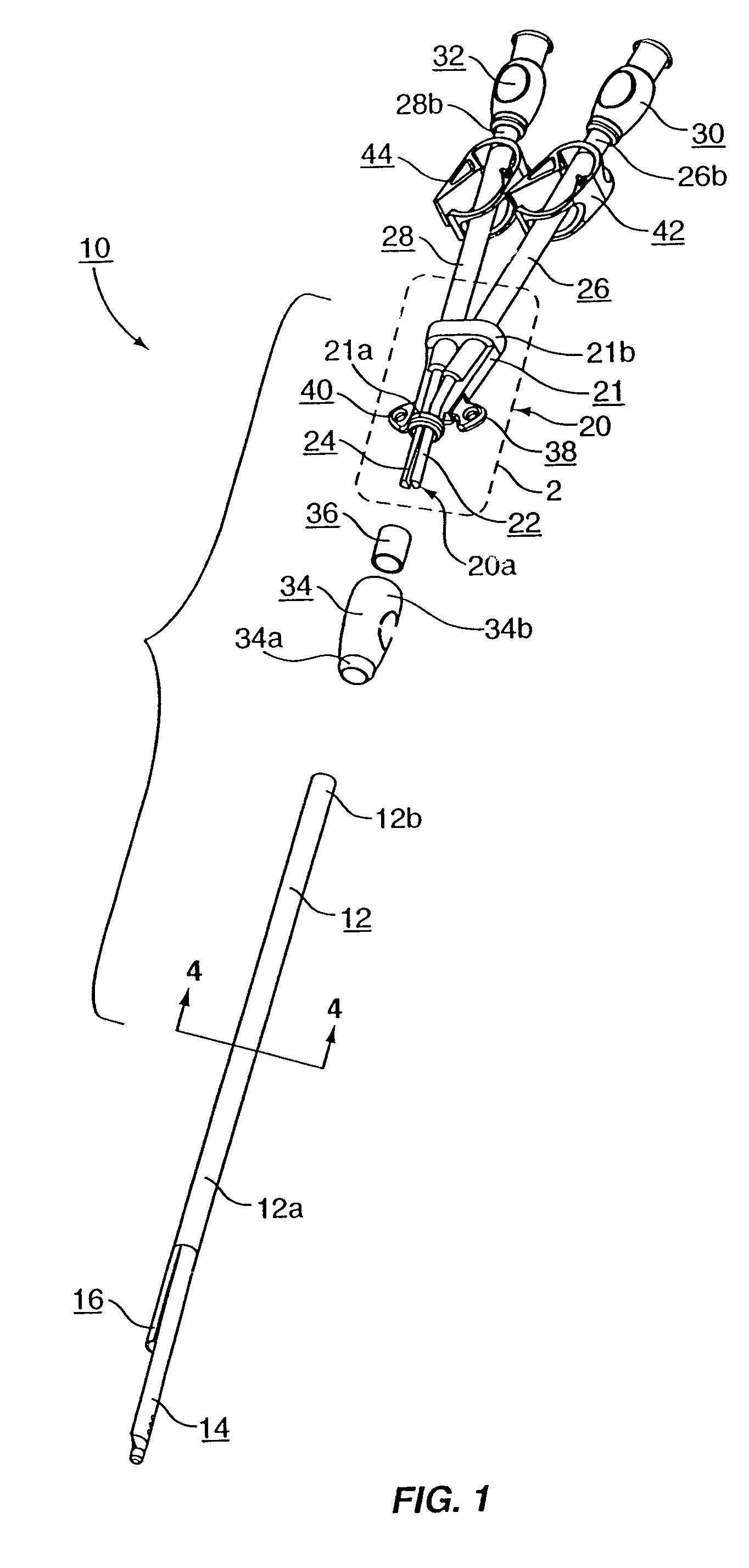
[0016]As shown in the Figures, the present invention is a multi-lumen catheter assembly 10 having a selectively attachable hub assembly 20. As shown in FIG. 1, a multi-lumen catheter tube 12 is formed with a proximal portion 12a and a distal portion 12b. The distal portion 12b of the catheter tube 12 is selectively attachable to the proximal portion 20a of the hub assembly 20. In this manner, the hub assembly 20 may be attached to the catheter tube 12 after insertion of the proximal portion 12a of the catheter tube, including tips 14 and 16, into a patient.

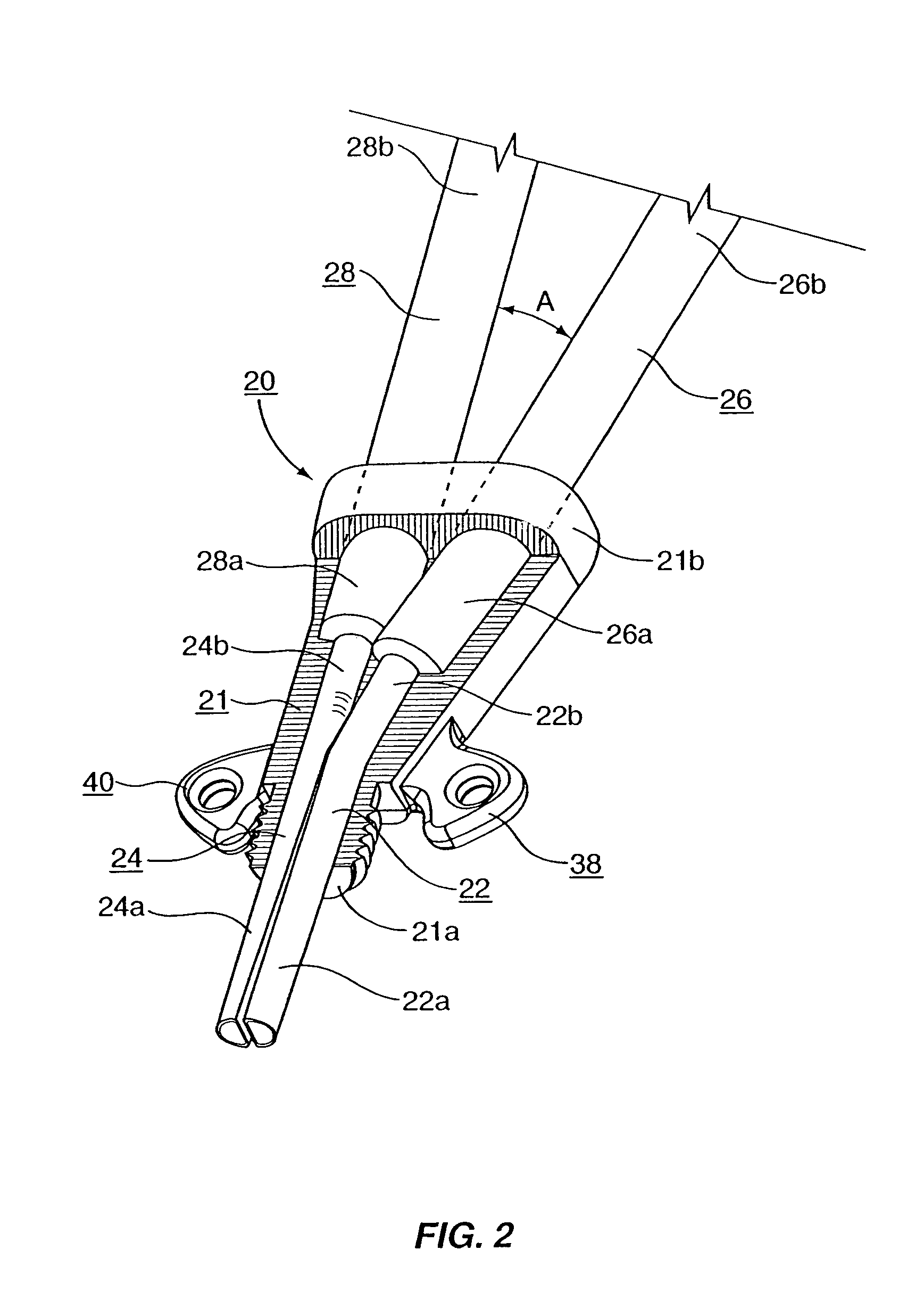
[0017]As illustrated in FIG. 2, preferably, the hub assembly 20 has a first cannula 22 and a second cannula 24. Each of the cannulae has a proximal portion 22a and 24a, respectively, and a distal portion 22b and 24b, respectively. Further, each cannulae 22 and 24 has an associated extension tube, 26 and 28 respectively. Each of the extension tubes 26 and 28 has a proximal portion 26a and 28a, respectively, and a distal portion 26b...


PUM


Abstract

A method of inserting a multi-lumen catheter assembly. First, an incision is made near the area to be catheterized. The proximal portion of the multi-lumen catheter tube is then inserted into the area to be catheterized. A subcutaneous tunnel is created, and the first end of the tunnel is near the incision. The catheter tube is then routed through the subcutaneous tunnel and pulled tube through a second end of the subcutaneous tunnel. The hub body is then securely attached to the catheter tube by connecting the connection cover to the hub body by threaded engagement. In a preferred embodiment the hub body is attached to the catheter tube by backfitting the connection cover over the catheter tube. A compression sleeve is also backfit over the catheter tube. The cannulae of the hub body are inserted into the lumens of the catheter tube to create fluid communication therebetween. The connection between the cannulae and the first and the catheter tube is compressed by sliding the compression sleeve over the cannulae that have been inserted into the catheter tube.

Description

RELATED APPLICATIONS[0001]This application is a Continuation of application Ser. No. 10 / 086,033, filed Feb. 28, 2002, now U.S. Pat. No. 6,638,242, the content of which is incorporated herein by reference in its entirety, which was a continuation of application Ser. No. 09 / 769,052, filed Jan. 24, 2001, now abandoned.FIELD OF THE INVENTION[0002]The present invention relates generally to medical instrumentation and more specifically to a method for inserting a multi-lumen catheter with a selectively attachable hub assembly that allows the catheter tip to be accurately positioned prior to subcutaneous tunneling.BACKGROUND OF THE INVENTION[0003]Catheters, generally, are hollow, flexible tubes for insertion into a body cavity, duct, or vessel to allow the passage of fluids or distend a passageway. Catheters are often used for temporary or long-term dialysis treatment. Dialysis treatment provides for blood to be withdrawn from the patient, purified, and then returned to the patient. Thus, ...

Claims


Application Information

Patent Timeline
Patent Type & Authority Patents(United States)
IPC IPC(8): A61M31/00A61M1/14A61M1/16A61M1/36A61M3/00A61M25/00A61M25/14A61M39/00
CPCA61M1/3653A61M25/0029A61M25/0097A61M1/3659A61M1/16A61M25/0028A61M2025/0031A61M2025/0034A61M2025/0037A61M2025/0098
Inventor WILSON, JON S.FLEMING, CARL M.CASSIDY, KENNETH T.BOYD, RONALD D.FLEMING, GARY S.
Owner TELEFLEX LIFE SCI LTD
Learn More