
Method for locking handle deployment mechanism with medical device

a technology of locking handle and medical device, which is applied in the field of medical devices, can solve the problems of blood flow, further disruption, and difficulty in deploying operations, and achieves the effects of improving the safety of patients, reducing the risk of infection, and reducing the safety of patients

Inactive Publication Date: 2008-06-03
CARDINAL HEALTH SWITZERLAND 515 GMBH
View PDF38 Cites 184 Cited by
  • Summary
  • Abstract
  • Description
  • Claims
  • Application Information

AI Technical Summary

Benefits of technology

The present invention is about a medical device delivery system with a better locking handle. The handle has a complicated mechanism that makes it easier to lock the device. This improves the efficiency and accuracy of the medical procedure.

Problems solved by technology

For several reasons, this deployment operation may require some measure of delicate skill.
For example, among these reasons is the dynamic blood flow at the desired site for treatment, which may be further disrupted by the presence of a lesion or stenosis to be treated.
If the physician's hand that holds the inner shaft hub does inadvertently move during deployment, it is possible that the medical device may be deployed in a non-optimum position.

Method used


Image

  • Method for locking handle deployment mechanism with medical device
  • Method for locking handle deployment mechanism with medical device
  • Method for locking handle deployment mechanism with medical device

Examples


Embodiment Construction

[0029]The following description of the preferred embodiments of the present invention is merely illustrative in nature, and as such it does not limit in any way the present invention, its application, or uses. Numerous modifications may be made by those skilled in the art without departing from the true spirit and scope of the invention.

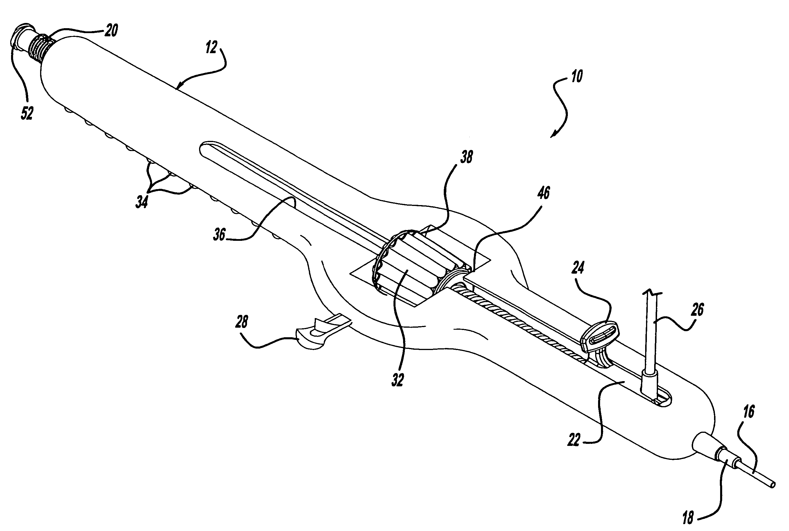
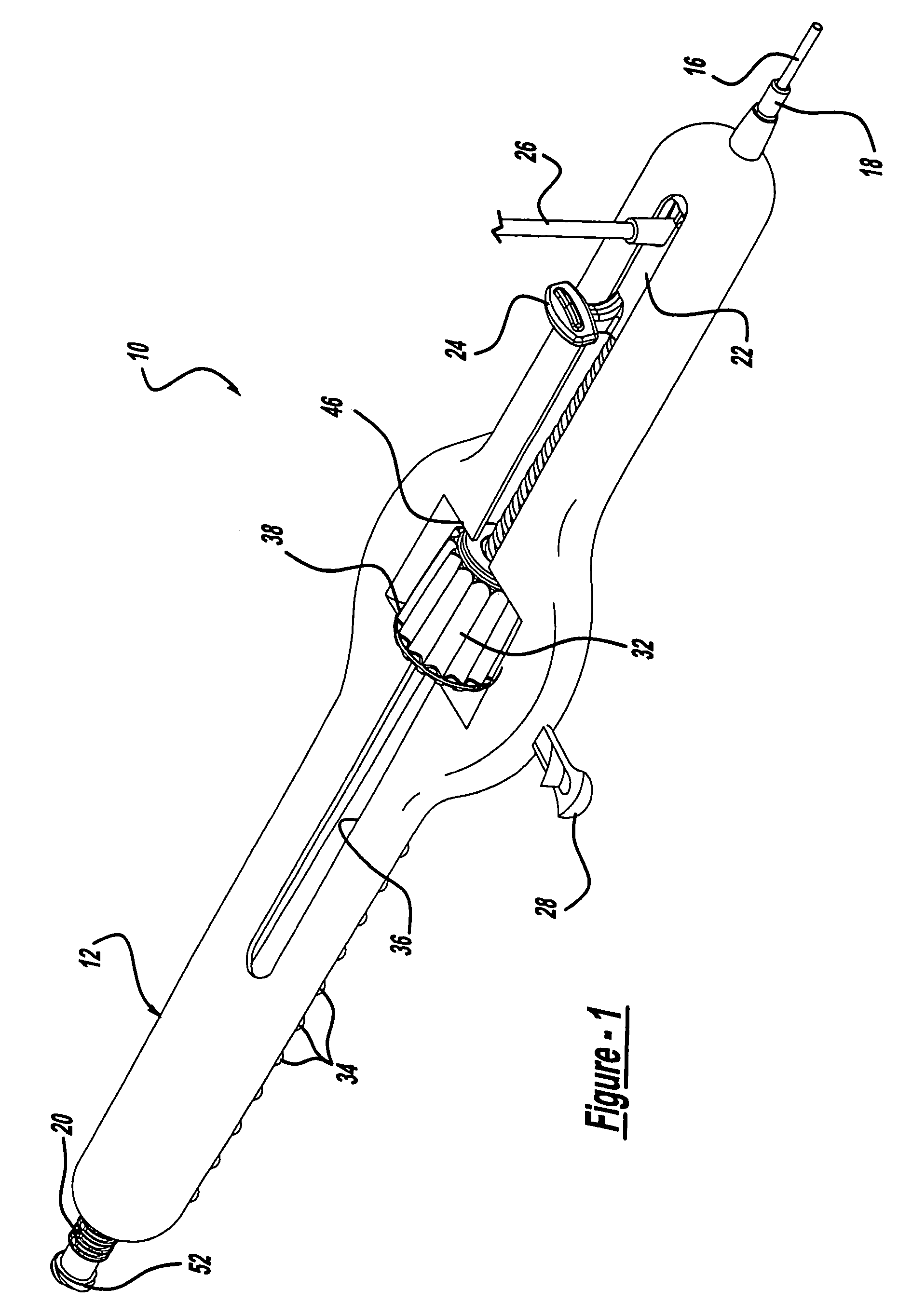
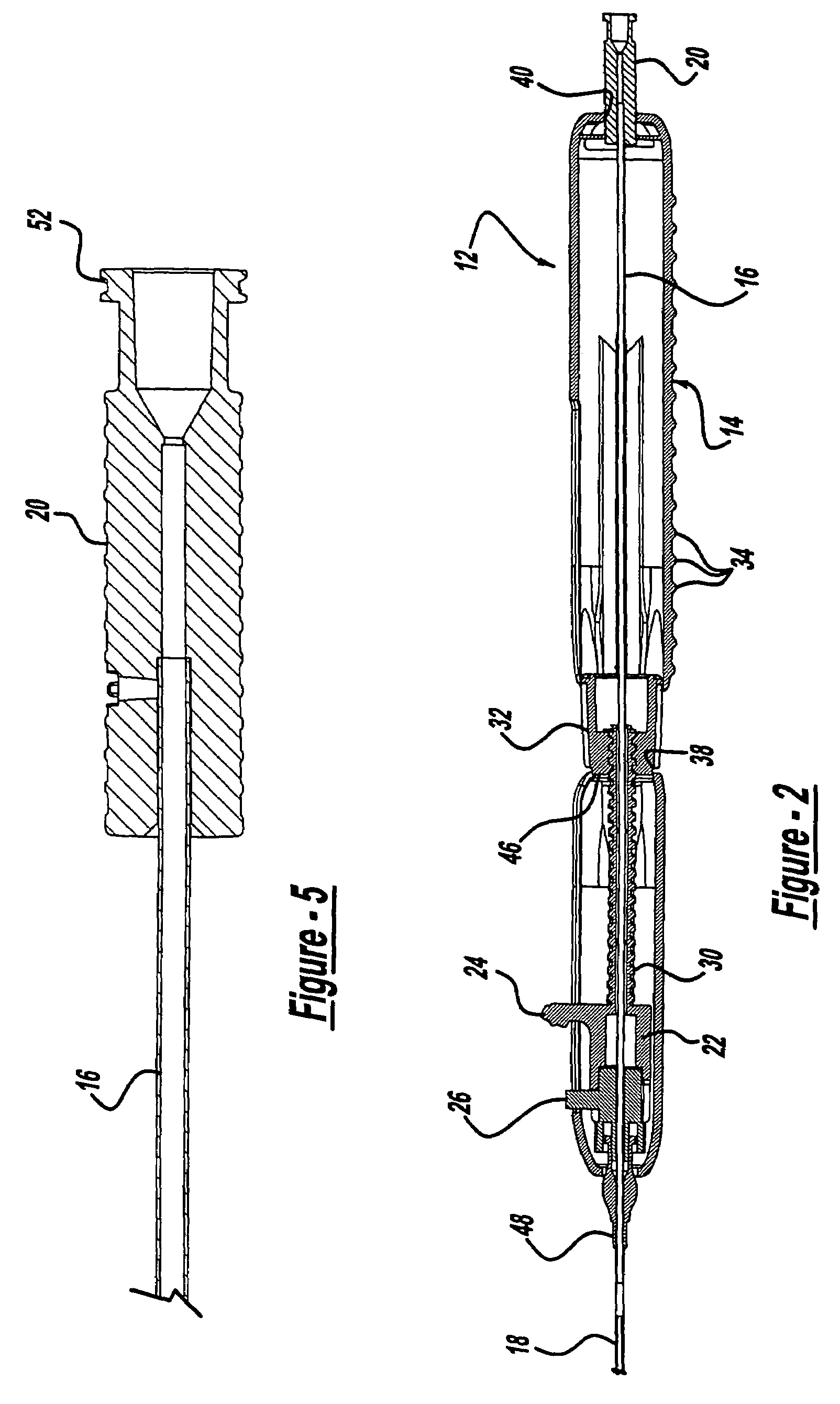
[0030]Referring to the drawings, a medical device delivery system is depicted, with one of the preferred embodiments of the present invention being shown at 10. The illustrated stent delivery catheter system 10 of course depicts only one of many different medical device delivery systems designs that are within the scope of the present invention. The present invention may be designed to deliver and deploy any suitable medical device. However, for clarity and convenience, the present detailed description will only describe such an example of a delivery system for stents.

[0031]Among the possible medical device delivery systems that may be used with the ...


PUM


Abstract

Methods for delivering at least one medical device to a desired location for treatment, and then selectively deploy it in position, include an improved handle. One of the possible features of the handle may be to selectively hold the delivery system components at any desired configuration during deployment and positioning of the medical device. Another possible feature of the handle may be more than one mode of operation, in which the deployment of the medical device can selectively proceed at more than one speed. Yet another possible feature of the handle may be a locking mechanism that resists inadvertent or accidental movement or retraction of the stent delivery system components during packaging, sterilization, shipping, storage, handling and preparation of the stent delivery system.

Description

REFERENCE TO RELATED APPLICATION[0001]This patent application is a divisional patent application of U.S. patent application Ser. No. 10 / 175,113 filed on Jun. 19, 2002 now U.S. Pat. No. 6,866,669, which is a continuation-in-part of U.S. patent application Ser. No. 09 / 975,873 filed on Oct. 12, 2001 now U.S. Pat. No. 6,939,352.BACKGROUND AND SUMMARY OF THE INVENTION[0002]1. Technical Background[0003]The present invention relates generally to medical devices, and more particularly to a medical device delivery system with an improved locking handle having a compound mechanism.[0004]2. Discussion[0005]The present invention involves medical devices, and also the delivery systems used to convey them to a desired location for treatment, and then deploy them in position. Many such medical devices are resiliently compressed to a smaller initial size for containment, protection, storage and eventual delivery from inside a catheter system. Upon deployment, the medical devices may resiliently exp...

Claims


Application Information

Patent Timeline
Patent Type & Authority Patents(United States)
IPC IPC(8): A61F2/06A61B17/00A61F2/82A61F2/84
CPCA61F2/95A61F2002/9517A61M2025/09116A61F2/9517
Inventor BUZZARD, JONFELLER, III, FREDERICK
Owner CARDINAL HEALTH SWITZERLAND 515 GMBH
Learn More