Transition between a rectangular waveguide and a microstrip line comprised of a single metallized bar

Active Publication Date: 2008-06-03
INTERDIGITAL CE PATENT HLDG
View PDF7 Cites 22 Cited by
  • Summary
  • Abstract
  • Description
  • Claims
  • Application Information

AI Technical Summary

Benefits of technology

[0008]The purpose of the invention is to propose a transition between a rectangular waveguide

Problems solved by technology

These embodiments of a transition between a waveguide structure and a planar structure prove to be relatively complex to realize and require the assembly of several parts that must be

Method used


Image

  • Transition between a rectangular waveguide and a microstrip line comprised of a single metallized bar
  • Transition between a rectangular waveguide and a microstrip line comprised of a single metallized bar

Examples


Embodiment Construction

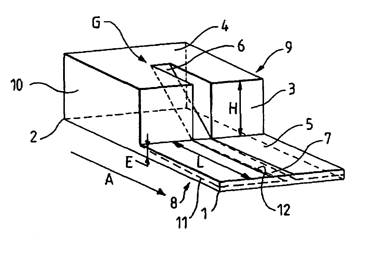
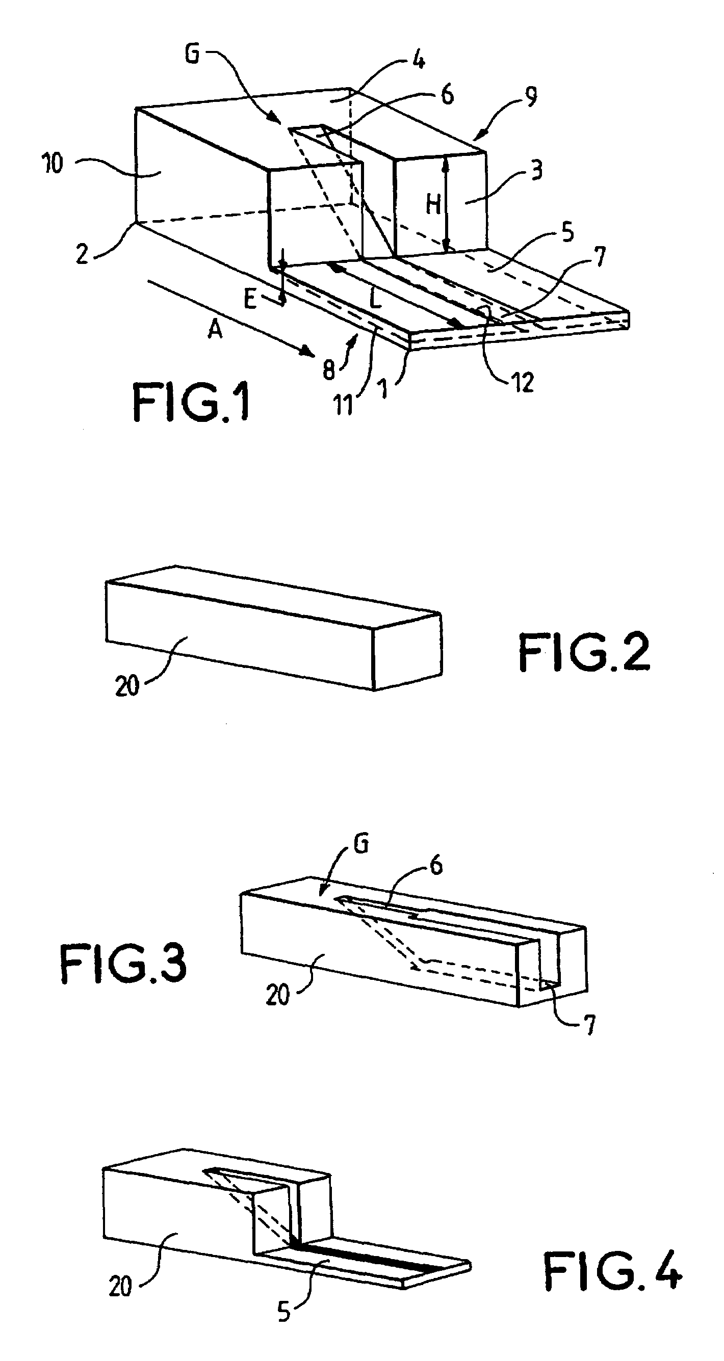
[0018]In FIG. 1, a transition between a rectangular waveguide and a microstrip line is constituted by a ribbed rectangular waveguide guide G realised in a foam bar of synthetic material that is also used as a substrate for the microstrip line.

[0019]As can be seen in FIG. 1, the foam bar of synthetic material, for example a polymethacrylate imide foam known for its electrical characteristics approaching those of air, for its mechanical characteristics of rigidity and lightness and for its low cost price, extends according to a longitudinal direction A between two extremities 1, 2 between which a shoulder 3 is formed that extends perpendicularly to the longitudinal direction A. This shoulder 3 defines an upper plane 4 of the ribbed waveguide and an upper plane 5 of the substrate. The upper plane 5 of the substrate is shifted perpendicular to the longitudinal direction of the bar of height H in relation to the upper plane 4 of the ribbed waveguide, the height H corresponding to the hei...


PUM

PropertyMeasurementUnit
Thicknessaaaaaaaaaa
Dimensionaaaaaaaaaa

Abstract

The transition between a rectangular waveguide and a microstrip line consists of a ribbed rectangular waveguide realised in a foam bar in synthetic material of which the metallized base under the rib continues in the form of a foam plate constituting a substrate for the microstrip line, the rib having a base extending between the upper plane of the ribbed waveguide and the upper plane of the substrate and the microstrip line being disposed on the upper plane of the substrate in the continuation of the base of the rib.

Description

[0001]This application claims the benefit, under 35 U.S.C. § 365 of International Application PCT / FR03 / 50201, filed Dec. 22, 2003 which was published in accordance with PCT Article 21(2) on Aug. 5, 2004 in French and which claims the benefit of French patent application No. 0300045, filed Jan. 3, 2003.FIELD OF THE INVENTION[0002]The invention relates to a transition between a rectangular waveguide and a microstrip line. Waveguide structures are often well adapted for the realization of small loss and high performance passive functions (antenna source such as corrugated horn antennas, polarizers, filters, diplexers) more particularly at very high frequencies (centimetric and millimetric bands). As for the planar structures, they are very well suited for the low cost, high volume production of devices integrating passive and active functions using the methods for manufacturing standard printed circuits for frequencies that can reach the millimetric bands. For example, in a satellite f...

Claims


Application Information

Patent Timeline
IPC IPC(8): H01P5/107
CPCH01P5/107Y10T29/49016H01P5/08
Inventor LO HINE TONG, DOMINIQUELOUZIR, ALIPERSON, CHRISTIANCOUPEZ, JEAN-PHILIPPE
Owner INTERDIGITAL CE PATENT HLDG
Why Eureka
Try Eureka