Rotatable binding apparatus for a snowboard

a technology of rotating apparatus and snowboard binding, which is applied in the direction of snowboard bindings, sports equipment, transportation and packaging, etc., can solve the problems of increasing and affecting the stability of the snowboard. , to achieve the effect of reducing the risk of injury to the legs, preventing or reducing excessive toe and heel drag

Inactive Publication Date: 2008-06-10
CERRITO PAUL
View PDF31 Cites 9 Cited by
  • Summary
  • Abstract
  • Description
  • Claims
  • Application Information

AI Technical Summary

Benefits of technology

[0012]It is a primary object of the invention to provide a snowboard binding mount that allows the boot binding of the front foot to be easily swiveled from a firmly fixed side forward (transverse) position to a firmly fixed toe forward (longitudinally aligned) position on the snowboard.
[0013]It is also an object of the invention to provide a snowboard binding mount that allows the boot binding of the front foot to be easily swiveled while providing a stable, substantially vibration free operation during active use.
[0015]It is also an object of the invention to reduce the risk of harm to the legs, knees, muscles and joints of the user of the snowboard by providing an improved rotating device for a snowboard binding for avoiding the need to remove a boot from a binding in order to avoid having to keep the leg bent in an unnatural position.
[0017]It is also an object of the invention to prevent or reduce excessive toe and heel drag that may occur when boots hang over the edge of the snowboard.

Problems solved by technology

There are periods when this side-forward (transverse) position becomes a problem for the snowboarder.
The snowboarder's body is left in an awkward, uncomfortable and twisted position as he or she attempts to move through flat terrain, and move onto the chairlift.
A rider can be on a chairlift longer than 15 minutes and this position can interfere with others on the chairlift as well as causing much strain and stress on the snowboarder's knee, leg, thigh and hip that are left in that side-forward position.
The previous attempts to address the need to move the position of the boot have generally involved complicated structures which did not result in a rotating binding that was relatively free of vibration during use, was not easy to operate and had disadvantages.

Method used


Image

  • Rotatable binding apparatus for a snowboard
  • Rotatable binding apparatus for a snowboard
  • Rotatable binding apparatus for a snowboard

Examples


Embodiment Construction

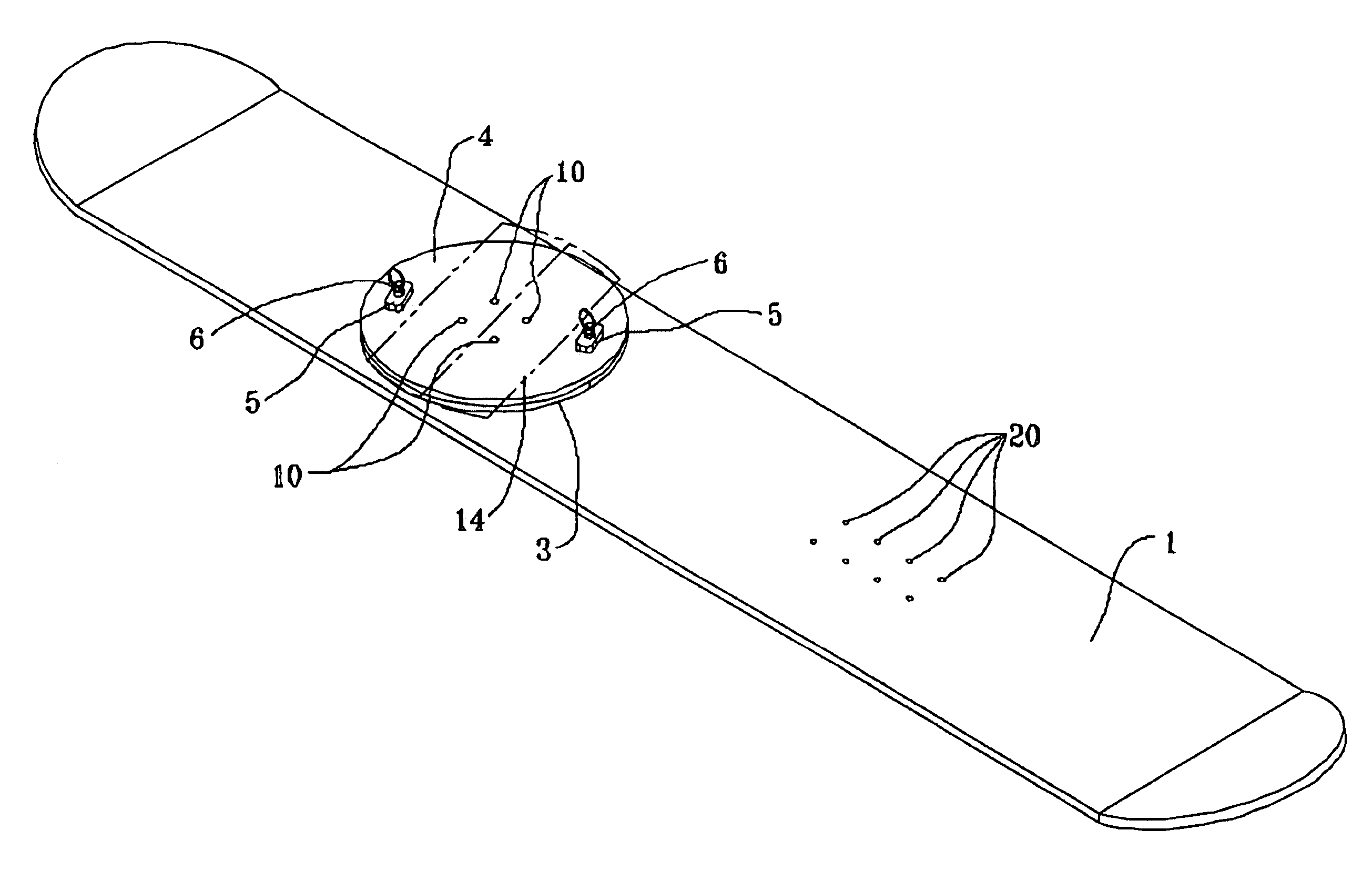
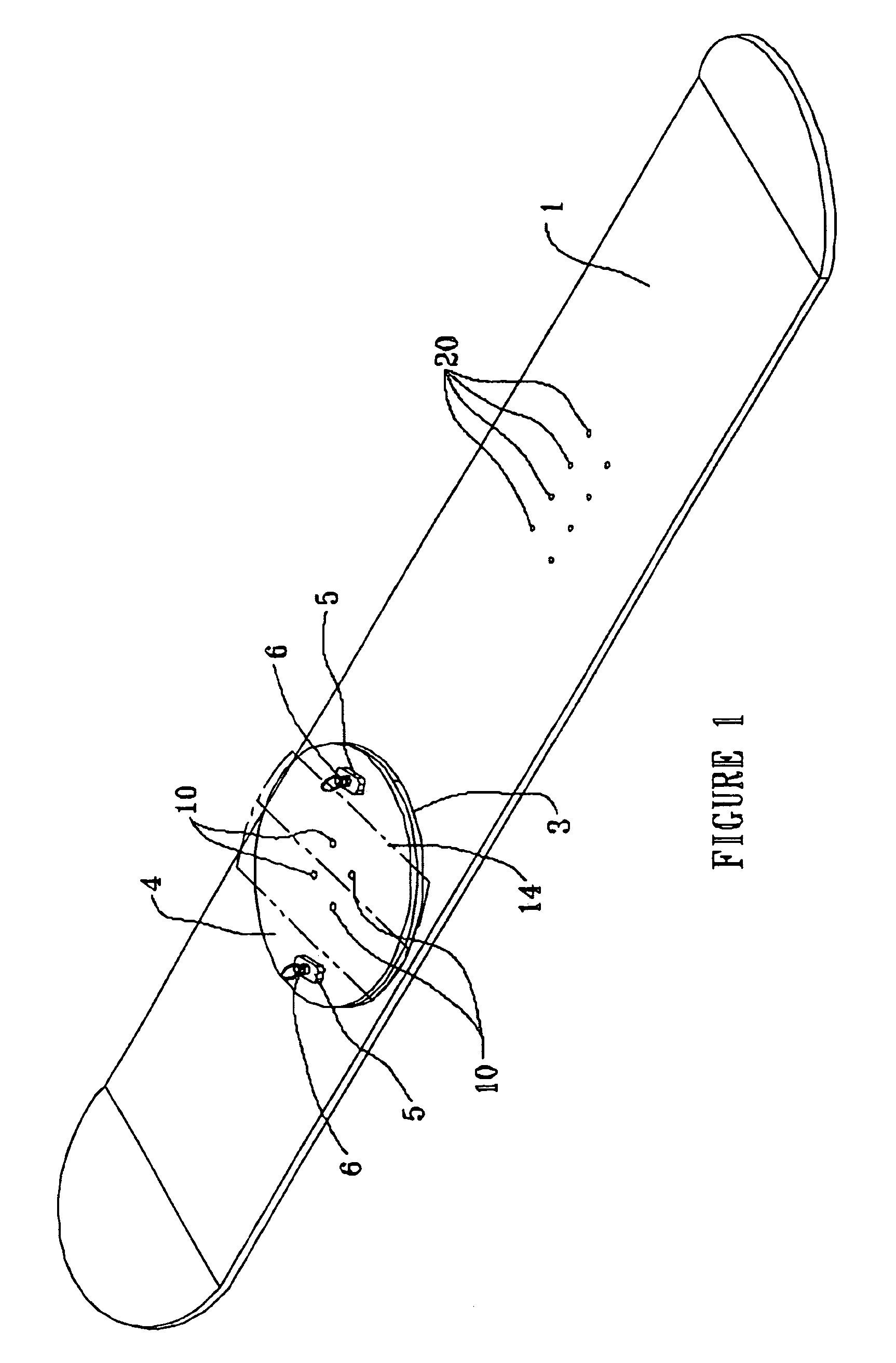
[0028]When a snowboarder removes the back boot from its binding to push the snowboard along a surface, the snowboarder can operate the rotatable binding of the invention by disengage the locking pins 6 in lock blocks 5 by pulling on pull cord or leash 27 as shown in FIG. 6. While the locking pins are disengaged, the binding mount of the front boot is rotated to position the boot in a toe-forward position. This toe-forward position prevents the thigh, the knee, the ankle and the associated muscles and ligaments from being subjected to an unnatural stress when the snowboard is pushed forward in a “skateboarding style”. When the snowboarder reaches a desired location for downhill boarding, pull cord 27 is retracted to withdraw locking pins 6 to permit the rotatable binding to be rotated to the side forward or transverse position.

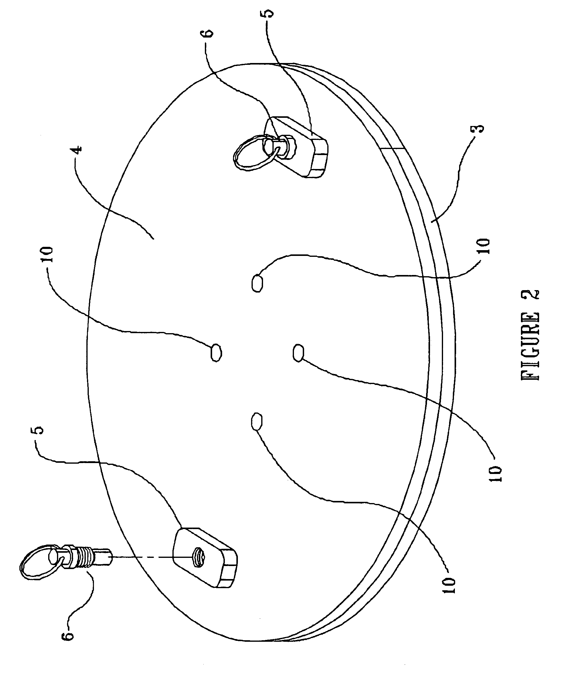
[0029]The first circular plate 2 functions as a swivel plate as it is not attached to the snowboard. The first circular plate 2 has on its upper surface a sect...


PUM


Abstract

A binding for affixing a boot to a snowboard that is being adapted to rotate between a plurality of fixed positions and having.(a) a first plate having plurality of holes between the top and bottom surfaces sized to engage fasteners. The first circular plate has a flange which mates with a flange on a second circular plate. The second plate has a centrally located hole that is sized to receive the first circular plate and having adjacent to the hole, a flange which is complimentary to the flange on the first plate. A third plate having a diameter which is substantially the same as the diameter of the second plate and which has a plurality of holes which are registerable with holes in the first plate. The third plate has a plurality of positions of the second plate relative to a longitudinal axis of a snowboard.

Description

BACKGROUND OF INVENTION[0001]1) Field of Invention[0002]This invention relates to a rotatable apparatus for snowboard bindings. It specifically relates to a simple binding that allows the front binding on a snowboard to swivel, without removing that front boot from the binding, and lock at pre-selected positions.[0003]2) Description of Prior Art[0004]In recent years, the sport of snowboarding has been growing in popularity. If this growth rate continues, snowboarding has the possibility of going past the popularity of downhill skiing. Young children are choosing snowboarding rather than downhill skiing as a beginning point for winter sports. Skateboarders of all ages are transferring their skills to the snowboard when they have the opportunity. Many skiers are even attempting to make the change to the newer, exciting sport of snowboarding. A snowboard is like a wide ski on which both feet are held to the board by two bindings that are set in a side-forward (transverse) stance. This ...

Claims


Application Information

Patent Timeline
Patent Type & Authority Patents(United States)
IPC IPC(8): B62B13/00
CPCA63C10/14A63C10/18
Inventor CERRITO, PAUL
Owner CERRITO PAUL
Why Eureka
Try Eureka