Maneuverable-coiled guidewire

a guidewire and coiled technology, applied in the field of maneuverability of coiled guidewires, can solve the problems of time-consuming, difficult, and difficult to direct the tip into the desired branch, and achieve the effect of easy maneuverability

Inactive Publication Date: 2004-05-13
INFRARED SCI
View PDF8 Cites 29 Cited by
  • Summary
  • Abstract
  • Description
  • Claims
  • Application Information

AI Technical Summary

Benefits of technology

0003] The present invention seeks to provide an easy maneuverability of a coated coiled guidewire around turns a

Problems solved by technology

At a bifurcation in the lumen it may be difficult to direct the tip into the desired branch.
Since the diameter of the guidewire

Method used


Image

  • Maneuverable-coiled guidewire
  • Maneuverable-coiled guidewire
  • Maneuverable-coiled guidewire

Examples


Embodiment Construction

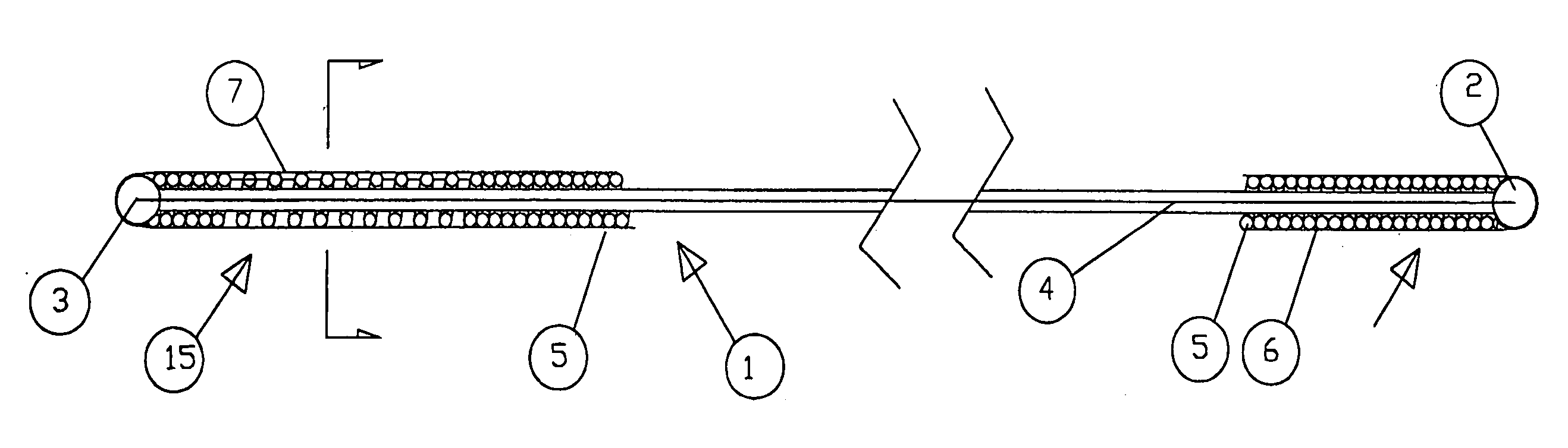
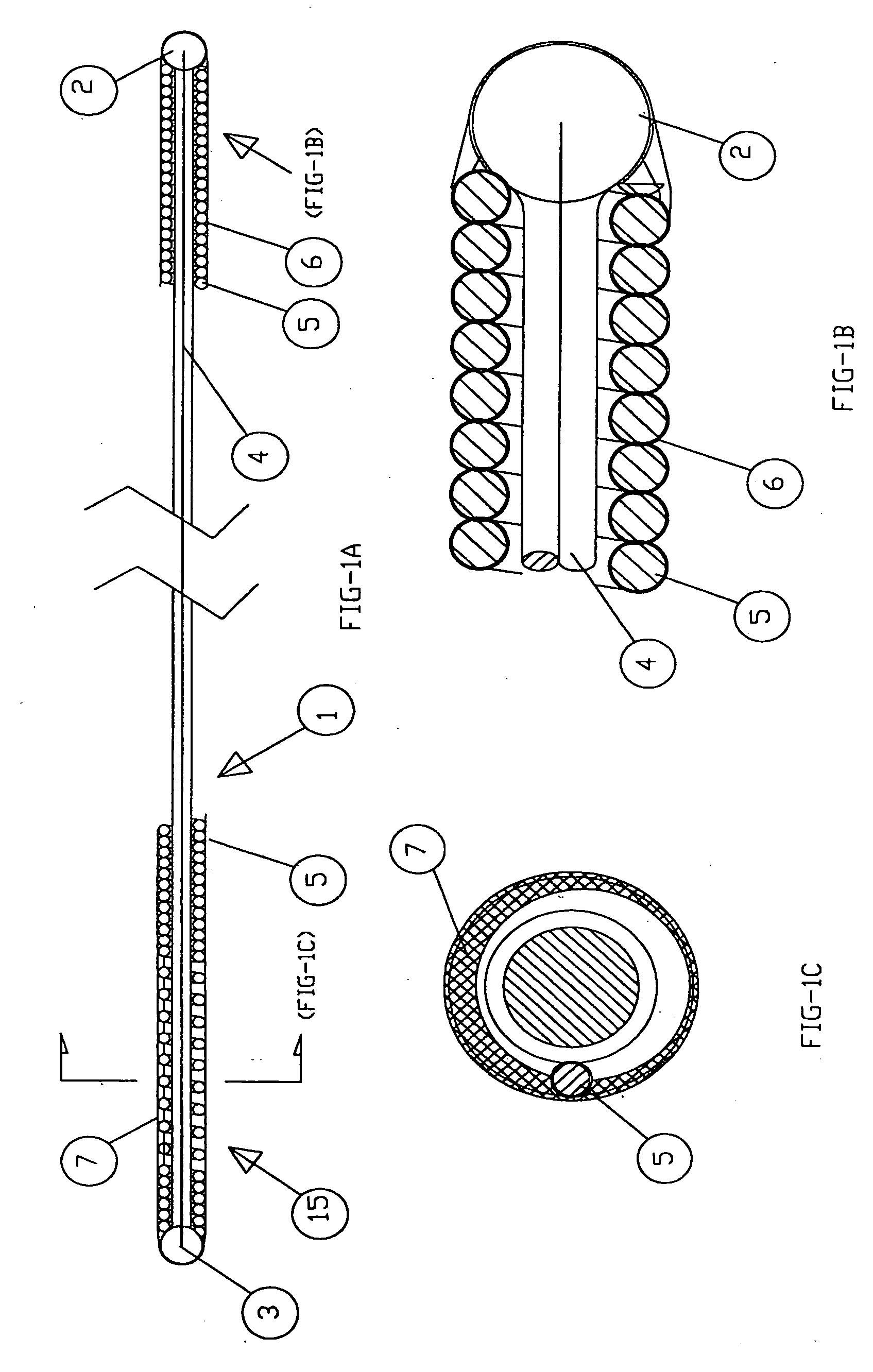
[0012] Reference is now made to FIGS. 1A-1C, which illustrate a maneuverable-coated coiled guidewire apparatus constructed and operative in accordance with an embodiment of the present invention.

[0013] The maneuvered-coated coiled guidewire apparatus may be constructed with a pull wire 4, disposed inside a coil 1, and connected at both ends thereof to a ball (first stop member) 2 at the proximal end and a ball (second stop member) 3 at the distal end. The coil 1 may be limited between ball 2 and ball 3. The coils 5 of coil 1 may be in touch with each other except for a part of the length of the coil, near the distal end marked by arrow 15, in which they may be spaced apart. A flexible coating 6, such as PTFE-Teflon, may coat the coil evenly except for the part 15 where the coils may be spaced apart, in which case the coating on one side of the coil may be deeper between the coils, as indicated by reference numeral 7. In other words, the coating 6 may be thicker on one side of the pe...


PUM


Abstract

Guidewire apparatus including a guidewire including a coil, a distal portion of the coil being coated with a flexible coating, the coating being thicker on one side of a perimeter of the distal portion than on an opposite side of the perimeter of the distal portion, a pull wire disposed inside the guidewire connected at a proximal end thereof to a first stop member and at a distal end thereof to a second stop member, and an actuator disposed on the guidewire adapted to move the pull wire proximally such that proximally-directed pulling on the distal portion of the coil bends the distal portion towards the opposite side of the perimeter of the distal portion.

Description

[0001] The present invention relates generally to guiding apparatus in general, and particularly to deflectable guiding apparatus of a coiled guidewire used to guide catheters within the body lumens in procedures such as percutaneous transluminal coronary angioplasty (PTCA).[0002] In order to facilitate the advancement of catheters through a body lumen (e.g., an artery), a guidewire is often used to guide the catheter. In some of the cases, a coated coiled guidewire is used, with or without pre-bending the distal tip. At a bifurcation in the lumen it may be difficult to direct the tip into the desired branch. In order to bent and rotate the guidewire the surgeon, using both hands, may manipulate the proximal end (protruding from the body) with his fingers. Since the diameter of the guidewire is very small and the area is slippery with blood, directing the tip to a desired angle is a difficult and time-consuming task.SUMMARY OF THE NVENTION[0003] The present invention seeks to provid...

Claims


Application Information

Patent Timeline
IPC IPC(8): A61M25/01A61M25/09
CPCA61M25/0147A61M2025/09116A61M2025/09091A61M25/09025
Inventor GABER, BENNY
Owner INFRARED SCI
Why Eureka
Try Eureka