

Magnetorheological fluid controlled mud pulser
a technology of magnetic fluid and pulser, which is applied in the direction of survey, directional drilling, borehole/well accessories, etc., can solve the problems of uncontrollable release of drill string fluid, erosion and wear caused by abrasive-laden drilling fluid, and negative pressure pulse techniques that are less than ideal
- Summary
- Abstract
- Description
- Claims
- Application Information
AI Technical Summary
Benefits of technology
Problems solved by technology
Method used
Image

Examples
Embodiment Construction
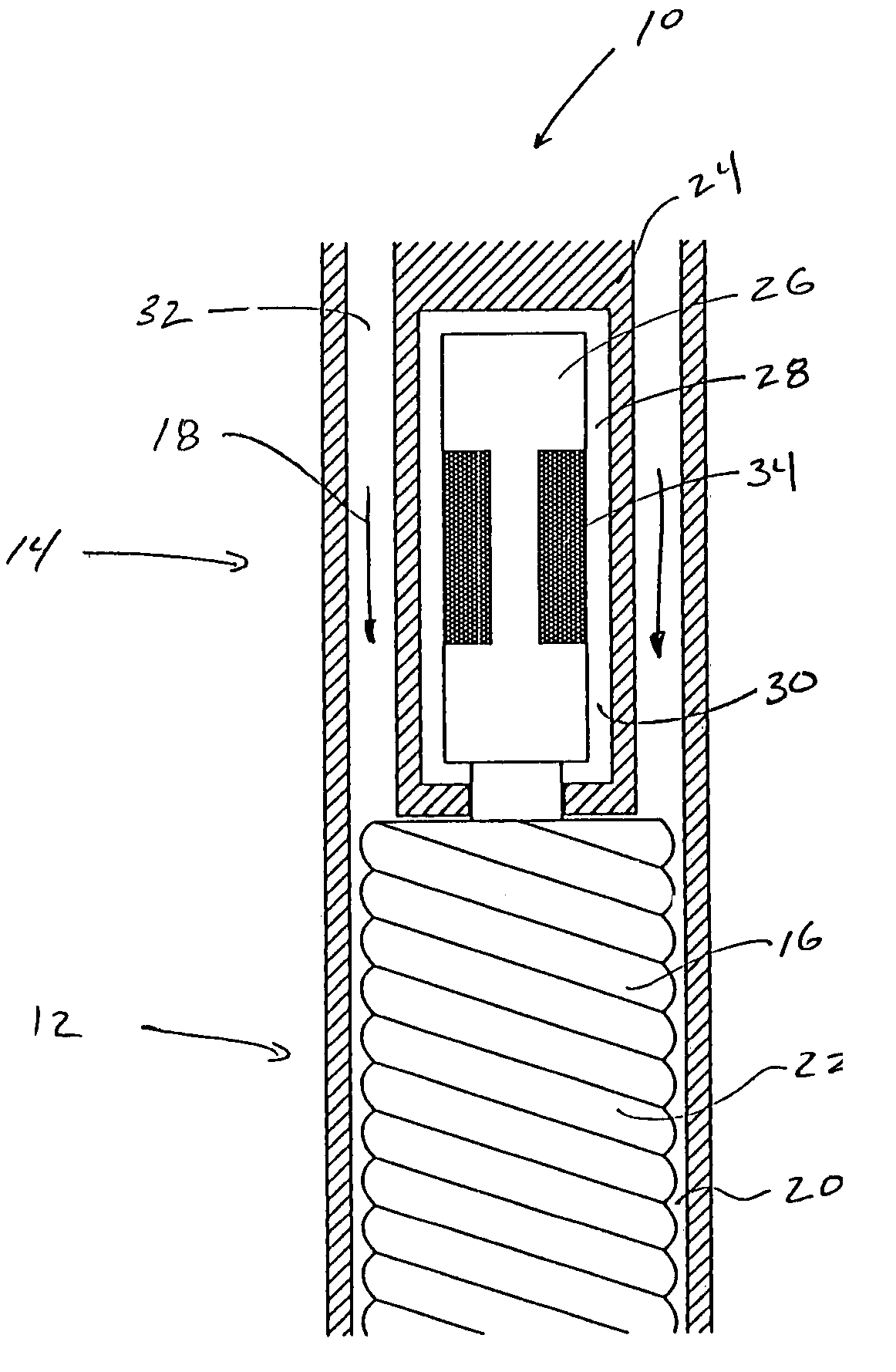
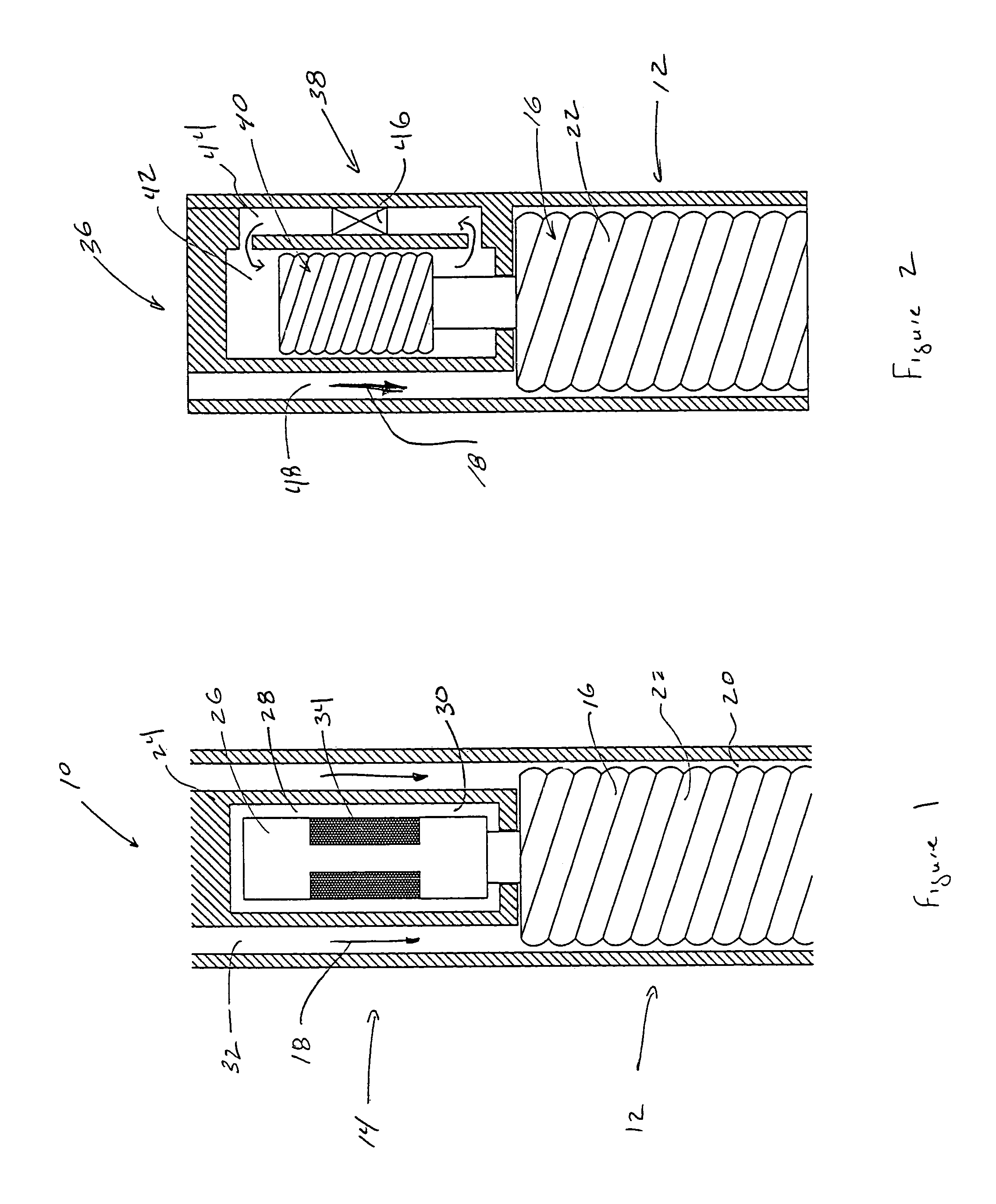
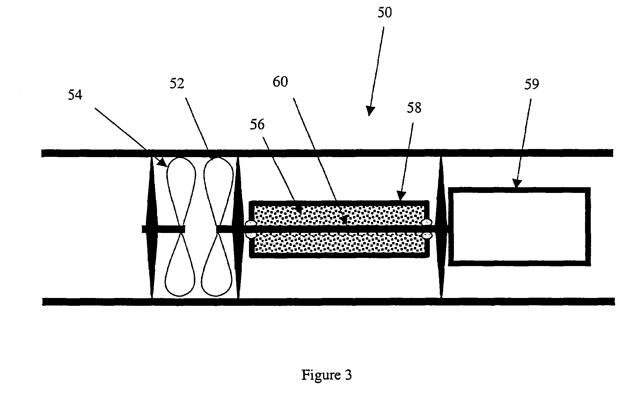
[0016]The preferred embodiments provide a mud pulser controlled by a field applied to an electroactive fluid. The electroactive fluid is employed to act as a rapid-response brake to interrupt the rotation of the rotor of a mud motor or mud siren, thus creating pressure pulses in the circulating fluid. In certain embodiments, the electroactive fluid is used as a direct brake, acting on a shaft rotating in a volume of electroactive fluid where the shaft is coupled to the rotor. The application of a field to the electroactive fluid impedes the rotation of the shaft, thus slowing the rotor and creating a pressure pulse in the circulating fluid. In another embodiment, a Moineau pump circulating electroactive fluid is coupled to the rotor. The application of a field to the electroactive fluid slows the rotation of the pump, thus slowing the rotor and creating a pressure pulse in the circulating fluid.
[0017]In one embodiment, the pressure pulser comprises a first body rotated by flowing fl...
PUM
| Property | Measurement | Unit |
|---|---|---|
| pressure | aaaaa | aaaaa |
| size | aaaaa | aaaaa |
| pressure transducer | aaaaa | aaaaa |
Abstract
Description
Claims
Application Information