Electric motorized hinge apparatus

a technology of motorized hinges and hinges, which is applied in the direction of multi-purpose tools, wing accessories, manufacturing tools, etc., can solve the problems of damage to the gear mechanism, the difficulty of manually the difficulty of manual opening and closing the lid parts, so as to avoid damage and promote miniaturization

Inactive Publication Date: 2005-03-10
COPAL CO LTD
View PDF10 Cites 31 Cited by
  • Summary
  • Abstract
  • Description
  • Claims
  • Application Information

AI Technical Summary

Benefits of technology

[0011] This electric motorized hinge apparatus is provided with the gear mechanism in view of the lack of torque of the motor itself and involves consideration to avoidance of damage to the gear mechanism and ease of rotation of the movable object during manual operation. When the motor is turned on in order to electrically rotate the movable object, the third rotating member starts rotating with rotation of the output shaft. On this occasion, the biasing means maintains a concavo-convex engagement state between the third rotating member and the second engagement portion in the second rotating member, so that the second rotating member also rotates to follow the third rotating member. Furthermore, the biasing means maintains a concavo-convex holding state between the first engagement portion in the second rotating member and the first rotating member, so that the first rotating member rotates to follow the second rotating member. Furthermore, as the first rotating member rotates, the movable object also rotates to follow it. In this manner, the rotating force of the output shaft is sequentially transferred from the third rotating member to the first rotating member. Even in a case where in the middle of electric rotation of the movable object the user forcedly stops the rotation, the third rotating member continues idling, while the engagement is released at the second concavo-convex engagement part having a holding force weaker than that of the first concavo-convex engagement part. As a consequence, the output shaft can continuously maintain rotation, so as to apply no excessive load to the gear mechanism, thereby avoiding an incident of damage to the gear mechanism. On the other hand, when the user manually rotates the movable object, the motor is maintained in an off state and the second rotating member is kept at a stop by the lock means. Therefore, the engagement state of the first concavo-convex engagement part is released by the manual rotation of the movable object, so that the movable object can be freely rotated by hand. The electric hinge apparatus of this structure involves the consideration to the two types of rotation operations consisting of the manual rotation and electric rotation of the movable object, while making up for the lack of torque of the miniature motor, and is extremely effective in promotion of miniaturization.

Problems solved by technology

However, the conventional electric motorized hinge apparatus described above had the following problem.
Namely, if the engagement force between projection and recess is set rather too strong, the concavo-convex engagement will become less likely to break in the electric opening / closing of the lid part, thus it will become harder to manually open and close the lid part.
Furthermore, if in the electric opening / closing of the lid part a user forcedly stops the opening / closing thereof, the gear mechanism can be damaged.
In this manner, the electric hinge apparatus requires consideration for satisfying both of avoidance of the damage to the gear mechanism and ease of opening / closing of the lid part in the manual operation, and thus had the problem that it was hard to miniaturize the apparatus, in view of the two types of opening / closing operations, the manual opening / closing and the electric opening / closing of the lid part.

Method used


Image

  • Electric motorized hinge apparatus
  • Electric motorized hinge apparatus
  • Electric motorized hinge apparatus

Examples


Embodiment Construction

[0024] The knowledge of the present invention can be readily understood in view of the following detailed description with reference to the accompanying drawings presented for illustrative purposes only. The following will describe embodiments of the present invention with reference to the accompanying drawings. The same portions will be denoted by the same reference symbols as much as possible, without redundant description.

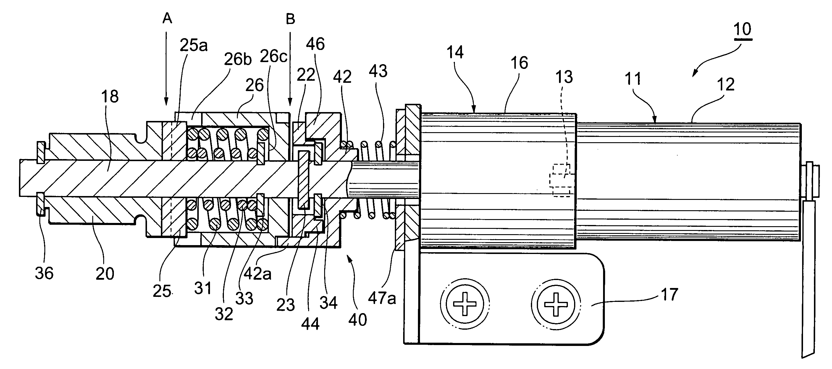
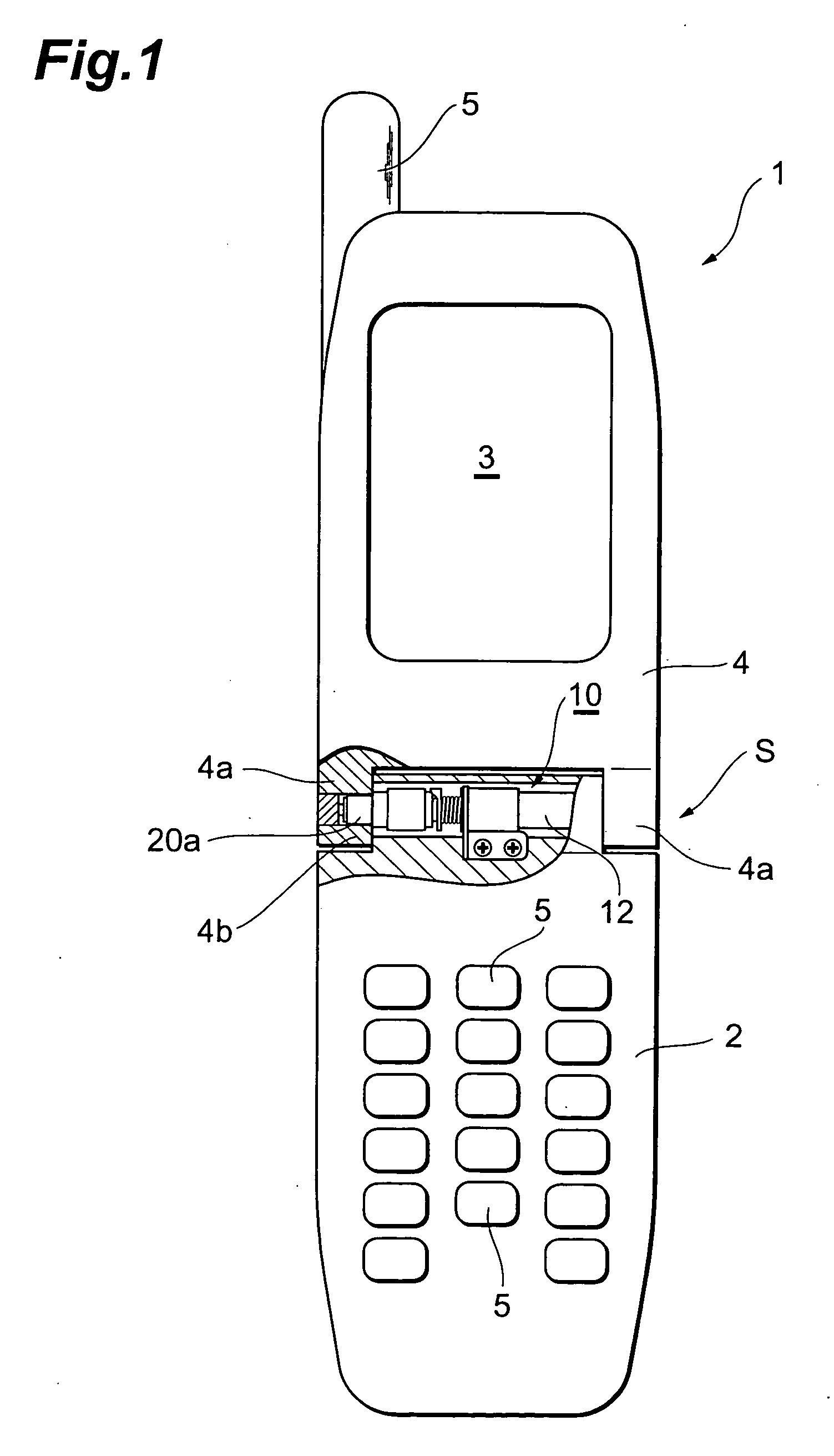
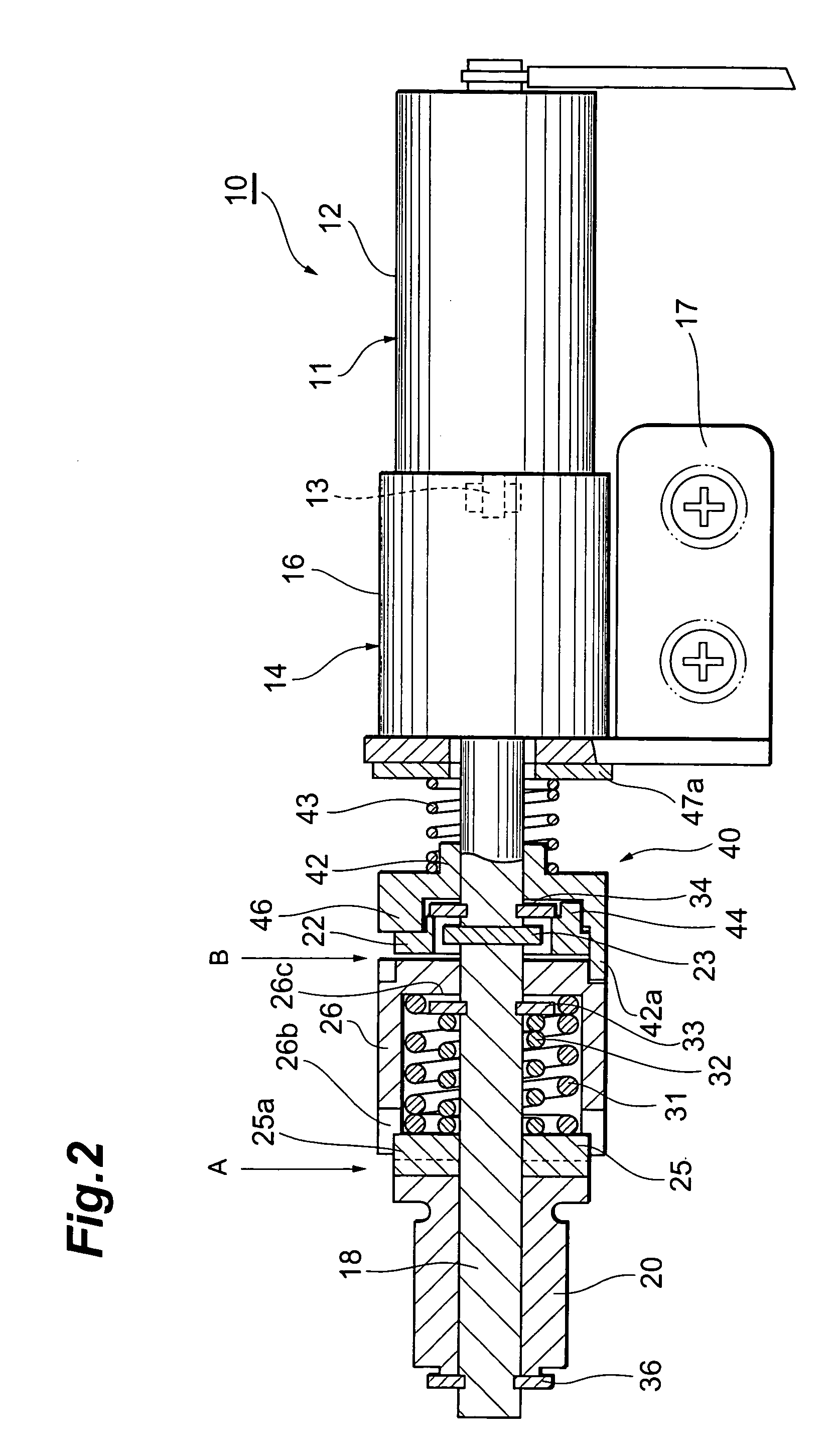
[0025] The electric motorized hinge apparatus according to the present invention is used in an opening / closing operation of a movable object (a lid or the like) mounted in the cell phones, personal digital assistants, notebook computers, etc. and endures application at a place of a narrow space. As shown in FIG. 1, a flip cell phone 1 is mainly composed of a main body 2 in which control buttons 5 of a numeric keypad and others are arranged, a lid portion (movable object) 4 in which a liquid crystal screen 3 is fitted, and an antenna 5 for transmission and recep...


PUM


Abstract

In an electric motorized hinge apparatus, a biasing means maintains a concavo-convex engagement state between a third rotating member and a second engagement portion in a second rotating member, and thus the second rotating member rotates to follow the third rotating member. Furthermore, the biasing means maintains a concavo-convex holding state between a first engagement portion in the second rotating member and a first rotating member, and thus the first rotating member rotates to follow the second rotating member. Furthermore, as the first rotating member rotates, a lid portion rotates to follow it. During manual rotation of the lid portion, a motor is maintained in an off state and the second rotating member is kept at a stop by a lock means. Therefore, the engagement state at the first concavo-convex engagement part is released by the manual rotation of the lid portion, so that the lid portion can be freely rotated by hand.

Description

BACKGROUND OF THE INVENTION [0001] 1. Field of the Invention [0002] The present invention relates to an electric motorized hinge apparatus utilized in an operation of opening and closing a lid or the like mounted, particularly, in cell phones, personal digital assistants, notebook computers, and so on. [0003] 2. Related Background Art [0004] The conventional technology in this field is one in Korean Utility Model No. 20-0174766. A cell phone described in this official gazette discloses an electric motorized hinge apparatus, and this hinge apparatus is housed in a hinge connection between the main body with a numeric keypad and a lid part (movable object) with a screen so as to enable electric opening and closing of the lid part of the cell phone. Since this hinge apparatus needs to be housed in the hinge part of the cell phone, a miniature motor is utilized. In consequence of the miniature motor, it is necessary to increase torque, and a geared motor is adopted in order to make up f...

Claims


Application Information

Patent Timeline
Patent Type & Authority Applications(United States)
IPC IPC(8): F16C11/10E05F15/12F16C11/04H04B1/38H04M1/02
CPCE05Y2201/214E05Y2201/244E05Y2900/606H04M1/0216E05F15/614Y10T16/541Y10T16/53883Y10T16/540247Y10T16/540243H04B1/38
Inventor TONOGAI, YOSHIHIDE
Owner COPAL CO LTD
Why Eureka
Try Eureka