Board to board connector

a technology of connectors and boards, applied in the direction of connections, electrical devices, printed circuits, etc., can solve the problem that the welding portion of the conductive terminal is difficult to be welded on the pcb

Inactive Publication Date: 2008-06-10
CHENG UEI PRECISION IND CO LTD
View PDF3 Cites 31 Cited by
  • Summary
  • Abstract
  • Description
  • Claims
  • Application Information

AI Technical Summary

Benefits of technology

[0008]As above description, the board to board connector can be welded on PCBs by the first and second locking pieces. While the plug is inserted into or pulled out from the rec

Problems solved by technology

It means that a welding portion of the conductive terminal is difficult to

Method used


Image

  • Board to board connector
  • Board to board connector
  • Board to board connector

Examples


Embodiment Construction

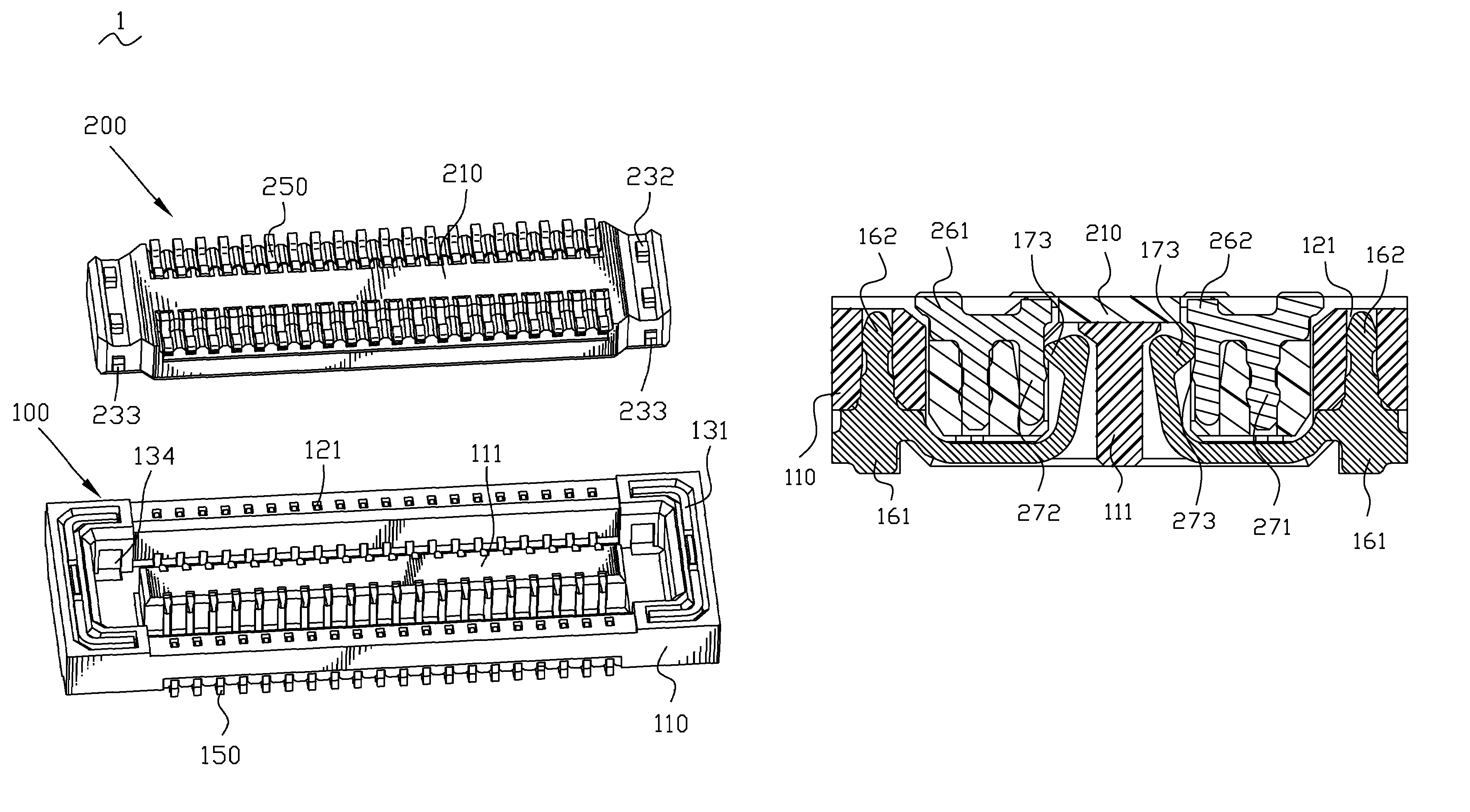
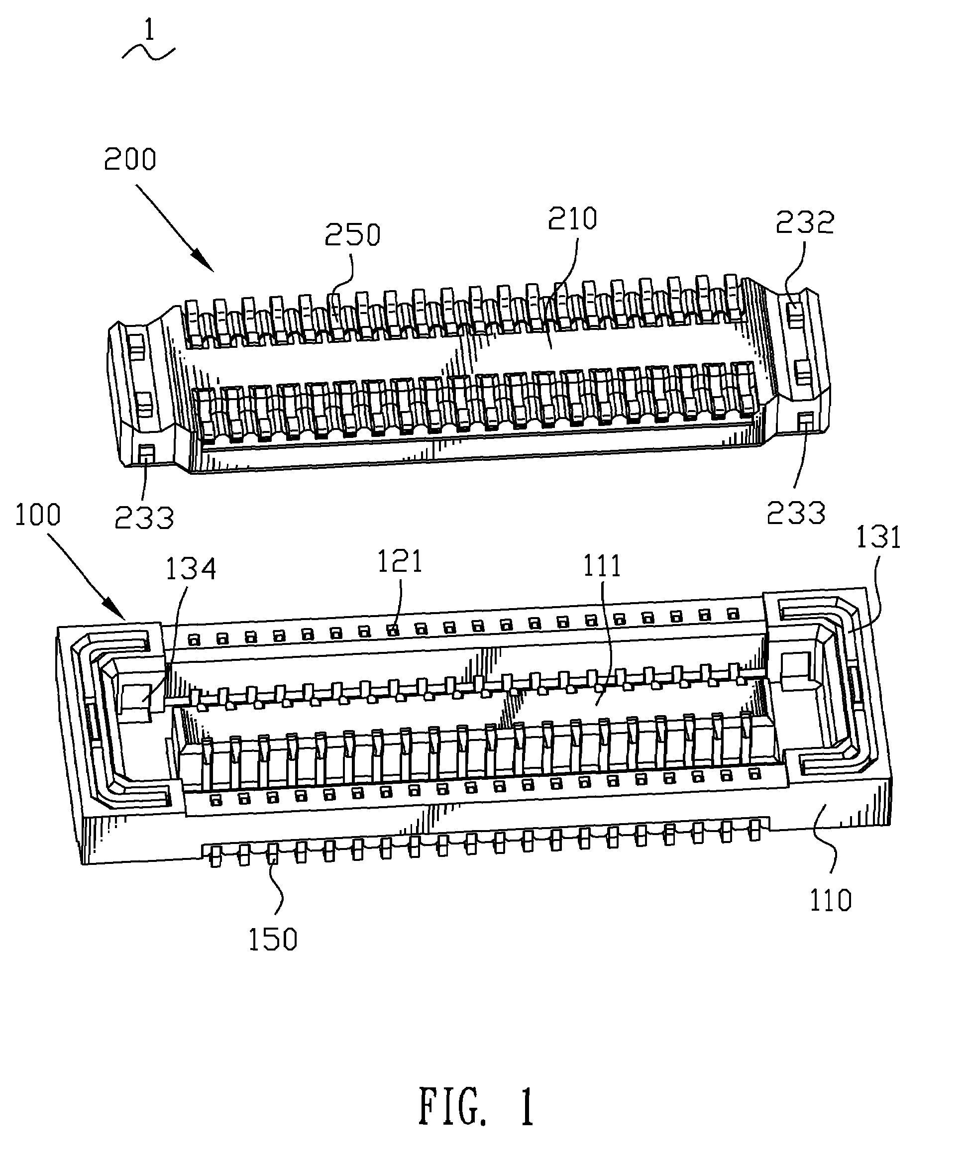
[0021]First referring to FIG. 1, a board to board connector 1 according to the invention is shown. The board to board connector 1 comprises a receptacle 100 and a plug 200 connected with the receptacle 100. The receptacle 100 and the plug 200 are respectively fixed on two PCBs (not shown). While the plug 200 is inserted into the receptacle 100, the two PCBs can deliver signal to each other.

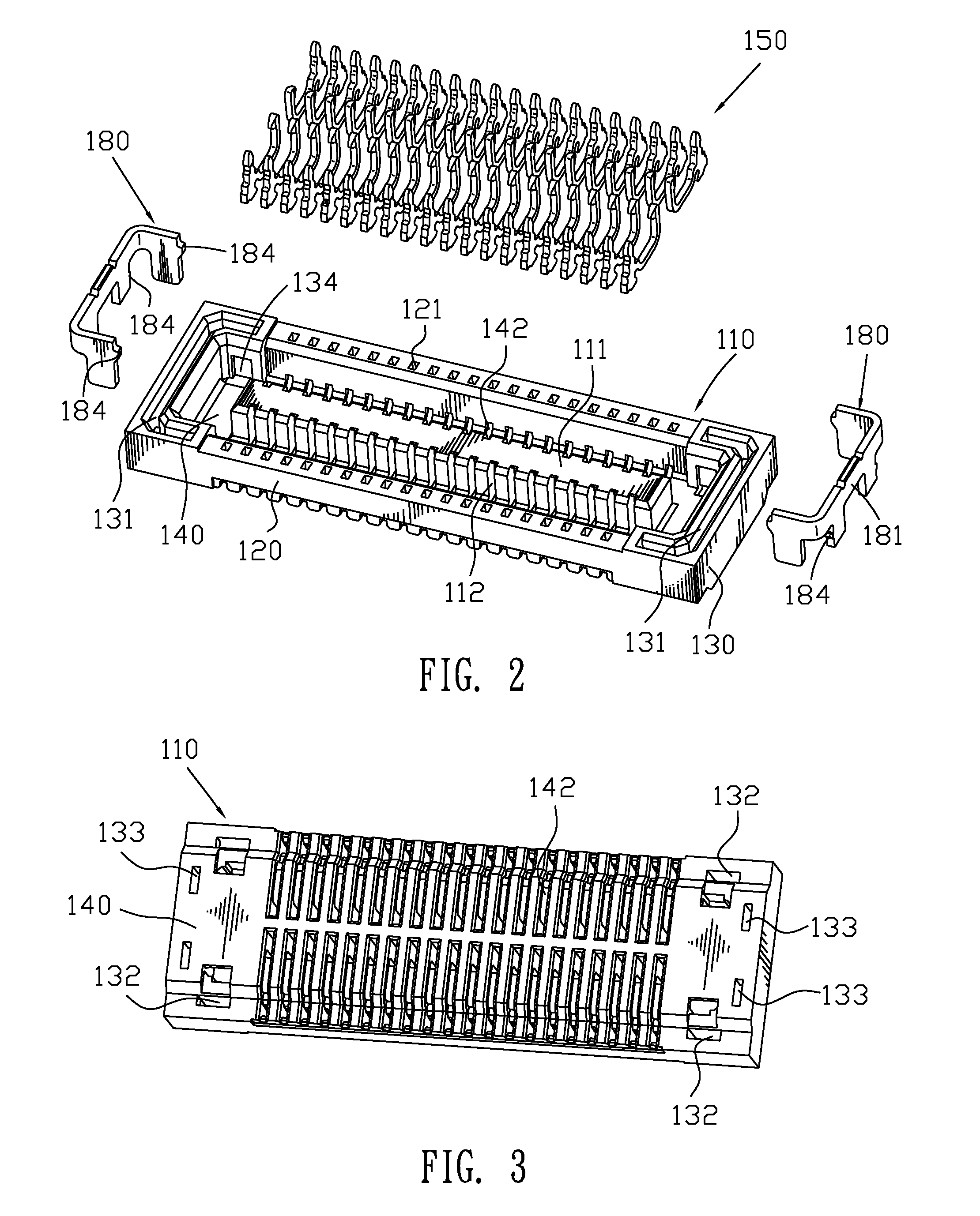
[0022]Please refer to FIGS. 1-3, the receptacle 100 includes a first housing 110, a plurality first terminals 150 received in the first housing 110, and a pair of first locking pieces 180 inserted in two ends of the first housing 110.

[0023]The first housing 110 has a base 140 showing a rectangular board shape. Two first side walls 120 project from two long edges of the base 140, two second side walls 130 project from two short edges of the base 140. The second side walls 130 are slightly taller than the first side walls 120. A projection 111 projects from the middle of the base 140 and is surround...


PUM


Abstract

A board to board connector includes a plug and a receptacle. The two ends of the receptacle sink to form a U-shape groove. The groove penetrates downward through the first housing of the receptacle and can accept a first locking piece. The first locking piece has a U-shaped body received in the groove, which extends to form welding portions, and the welding portions project out of the first housing. An inserting groove is opened in the end of the plug. The inserting groove can accept a second locking piece. A straight arm of the second locking piece projects out of the second housing of the plug. The board to board connector can be welded in PCBs by the first and second locking pieces.

Description

BACKGROUND OF THE INVENTION[0001]1. Field of the Invention[0002]This present invention relates to a board to board connector, and more specifically to a board to board connector which can be welded firmly on PCBs.[0003]2. The Related Art[0004]Conventionally, a board to board connector is arranged in an electric product to deliver signals between two PCBs.[0005]A traditional board to board connector includes a receptacle and a plug. The receptacle and the plug are respectively welded on PCBs via a plurality of conductive terminals located in the receptacle and the plug. While the plug connector is inserted into the receptacle, the two PCBs can deliver signals therebetween.[0006]As the volume of electric products is reduced, the conductive terminals are reduced correspondingly. It means that a welding portion of the conductive terminal is difficult to be welded on the PCB, because the area of the welding portion is too small. Particularly, the plug connector is inserted into or remove...

Claims


Application Information

Patent Timeline
IPC IPC(8): H01R12/00
CPCH01R12/714H01R12/716H01R12/7005H01R12/57H01R12/707
Inventor CHEN, CHUNG-YUYANG, MEI-CHUANHUANG, CHUNG-HSIN
Owner CHENG UEI PRECISION IND CO LTD
Why Eureka
Try Eureka