Tip-in/tip-out gear shift control for a powershift automatic transmission

a technology of automatic transmission and gear change, which is applied in the direction of mechanical equipment, transportation and packaging, etc., can solve the problems of inability to complete the shift in time, long time, and difficult to handle the change-of-mind gear shift, so as to eliminate the change-of-mind shift and improve the effect of the shi

Inactive Publication Date: 2008-06-10
FORD GLOBAL TECH LLC
View PDF23 Cites 17 Cited by
  • Summary
  • Abstract
  • Description
  • Claims
  • Application Information

AI Technical Summary

Benefits of technology

[0005]The control of this invention eliminates change-of-mind shifts instead of improving them. It enables the powershift transmission to provide the best change-of-mind shift quality and the desired wheel torque the driver wants and expects. It also enables the transmission to provide the best response to the driver demanded tip-in and tip-out.

Problems solved by technology

Change-of-mind gear shifts are very difficult to handle in a powershift transmission, and they require a relatively long period to complete due to the need for coordinated engagement and disengagement of several synchronizers or couplers during the shift.
Such shifts cause the operator to sense a lengthy, unacceptable delay in completing the shift, and the shift may be accompanied by a bump or harsh shift feel.
Vehicle occupants regard such sensations as unacceptable shift quality.

Method used


Image

  • Tip-in/tip-out gear shift control for a powershift automatic transmission
  • Tip-in/tip-out gear shift control for a powershift automatic transmission
  • Tip-in/tip-out gear shift control for a powershift automatic transmission

Examples


Embodiment Construction

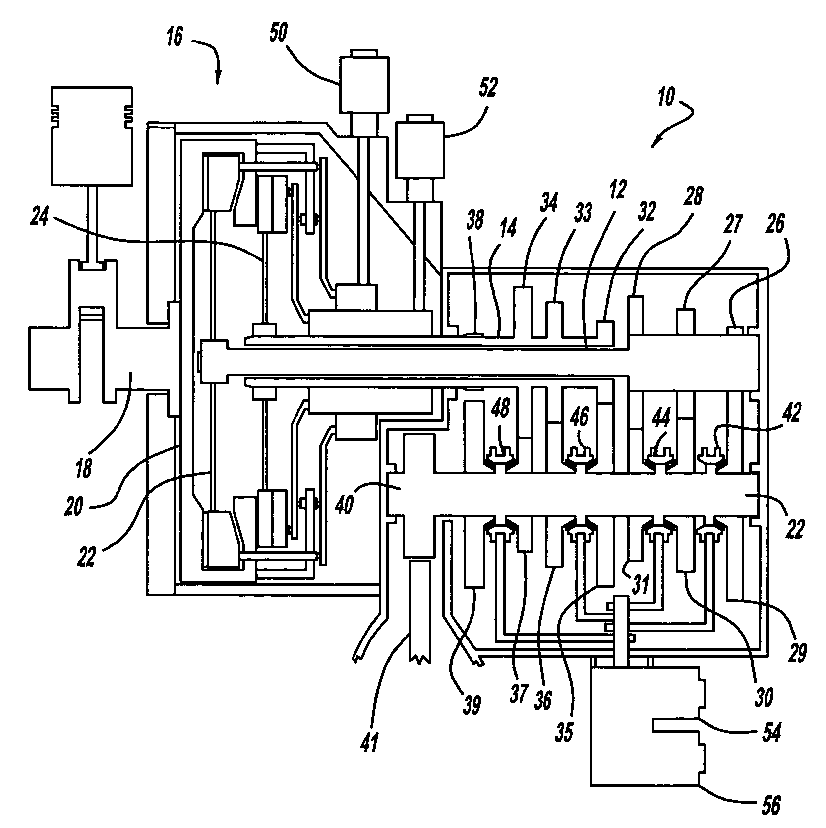
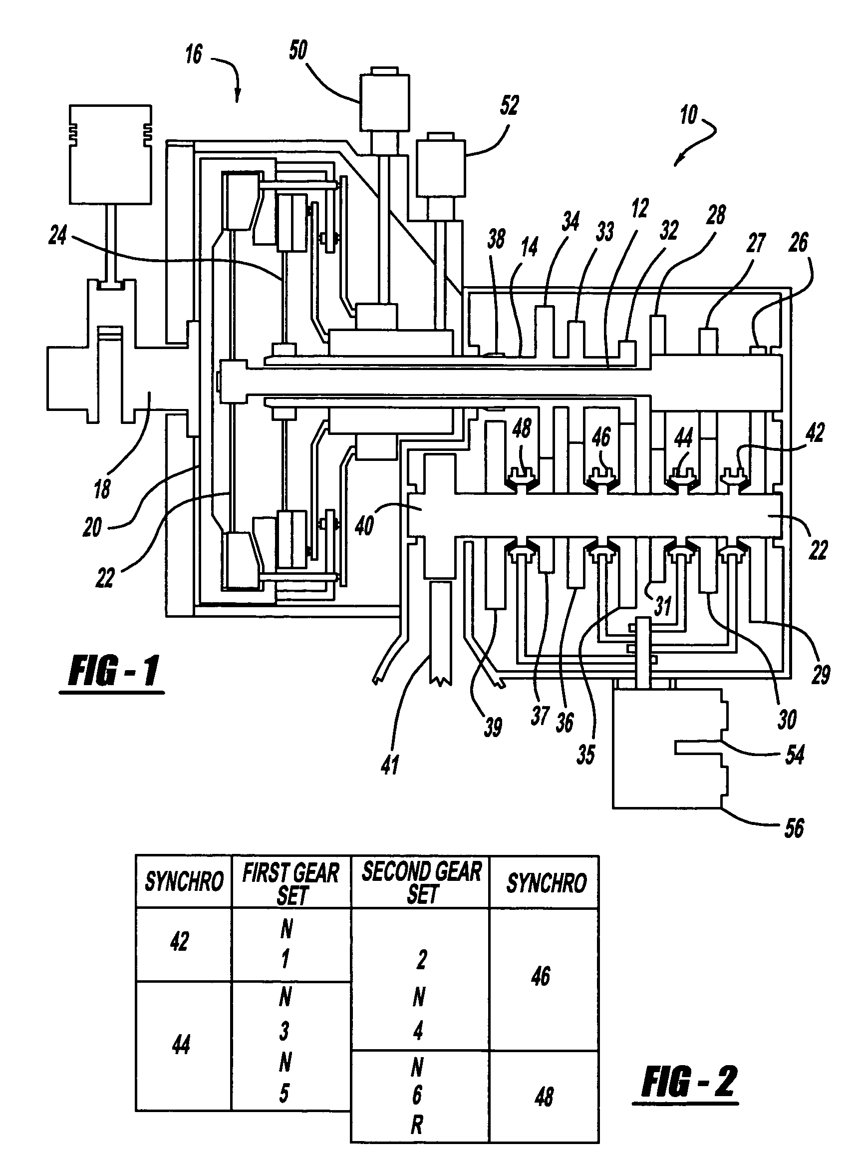
[0014]Referring now to FIG. 1, the powershift transmission 10 includes a first input shaft 12 associated with the odd-numbered forward speed ratios, and a second input shaft 14 associated with the even-numbered forward speed ratios and reverse drive. Input shaft 14 is a sleeve shaft surrounding input shaft 12. A dual clutch mechanism 16 produces a drive connection between the crank shaft 18 of an engine or another power source to the first and second input shafts 12, 14. The clutch mechanism 16 includes a flywheel 20, which is driveably connected to crankshaft 18 and is alternately driveably connected to and disconnected from input shaft 12 when clutch 22 is engaged and disengaged, respectively. Flywheel 20 is alternately driveably connected to and disconnected from input shaft 14 when clutch 24 is engaged and disengaged, respectively.

[0015]Preferably input shaft 12 is formed with pinions 26, 27, 28 for the first, second, and third speed ratios. Each pinion 26-28 is in meshing engag...


PUM


Abstract

A method for shifting a transmission from a current gear to a target gear following release of an accelerator pedal, the transmission having first and second clutches for alternately connecting and disconnecting a power source and first and second input shafts, respectively, first couplers for alternately connecting and disconnecting a transmission output and a first set of gears driveably connected to the first clutch, and second couplers for alternately connecting and disconnecting the output and a second set of gears driveably connected to the second clutch. The steps include disengaging the first and second clutches, using a first coupler to maintain a drive connection between the output and the current gear, determining a target gear, using the target gear to determine a preselected gear, actuating a coupler to produce a drive connection between the output and the preselected gear, and engaging one of the first and second clutches such that said clutch driveably connects the power source to the output through said coupler and preselected gear.

Description

BACKGROUND OF THE INVENTION[0001]The present invention relates to the control of gear changes in an automatic transmission for a motor vehicle. More particularly, it pertains to a strategy for controlling gear changes following a change-of-mind event in a powershift transmission.[0002]A change-of-mind shift occurs when the operator of a motor vehicle equipped with an automatic transmission depresses the accelerator pedal, called a “tip-in,” and immediately releases the pedal, called a “tip-out” or “back-out.” A change-of-mind shift can occur also when the vehicle operator releases the accelerator pedal, then immediately depresses the pedal. If the transmission were operating in third gear when the change-of-mind event occurs, an upshift through several gears to sixth gear might be immediately followed by a downshift to third gear. Change-of-mind gear shifts are very difficult to handle in a powershift transmission, and they require a relatively long period to complete due to the nee...

Claims


Application Information

Patent Timeline
Patent Type & Authority Patents(United States)
IPC IPC(8): F16H59/48B60W10/10B60W10/02
CPCF16H61/0437F16H61/688F16H3/006F16H2061/0448Y10T74/19288F16H2306/24Y10T477/692Y10T477/688F16H2200/0052F16H61/0403
Inventor JIANG, HONG
Owner FORD GLOBAL TECH LLC
Why Eureka
Try Eureka