Metronome with projected beat image

a technology of magnetome and projection image, applied in the field of magnetomes using light, can solve the problems of unfavorable live performances or recordings

Inactive Publication Date: 2008-06-10
BORNSTEIN DAVID A +1
View PDF42 Cites 12 Cited by
  • Summary
  • Abstract
  • Description
  • Claims
  • Application Information

AI Technical Summary

Benefits of technology

[0009]The present invention overcomes the disadvantages of the prior art by providing a system and method for projecting a visual queue to a conveniently viewable surface so as to indicate a tempo or a rhythm such that one or more musicians may be synchronized without requiring auditory interference, headphones, multiple devices, and / or a direct line of sight to the device. The present invention also provides a continuous visual indication of the progress of the tempo such that a musician may anticipate a beat.

Problems solved by technology

Furthermore, the clicking sound may be undesirable for live performances or recordings.
The flashing lights and / or the speaker share the primary disadvantages of the rod and the clicking sound of traditional pendulum metronomes; namely, these indicators work well only for those musicians within direct view of the metronome, and the auditory queue may be undesirable for live performances or recordings.
Furthermore, a flash of light and / or a single auditory queue gives no information to the musician as to how time is progressing between beats.
Also, the light may be out of view of a vast number of the musicians in a large ensemble.
Although sending the auditory queue via headphones may overcome some of the disadvantages of prior metronome designs, this solution requires additional equipment, such as additional wiring, additional connections, and a set of headphones for each musician.
All of this additional equipment adds complexity, expense, potential distraction, and new potential points of failure to prior systems.
Furthermore, an auditory queue via headphones still gives no information to the musician as to how time is progressing between beats.

Method used


Image

  • Metronome with projected beat image
  • Metronome with projected beat image
  • Metronome with projected beat image

Examples


Embodiment Construction

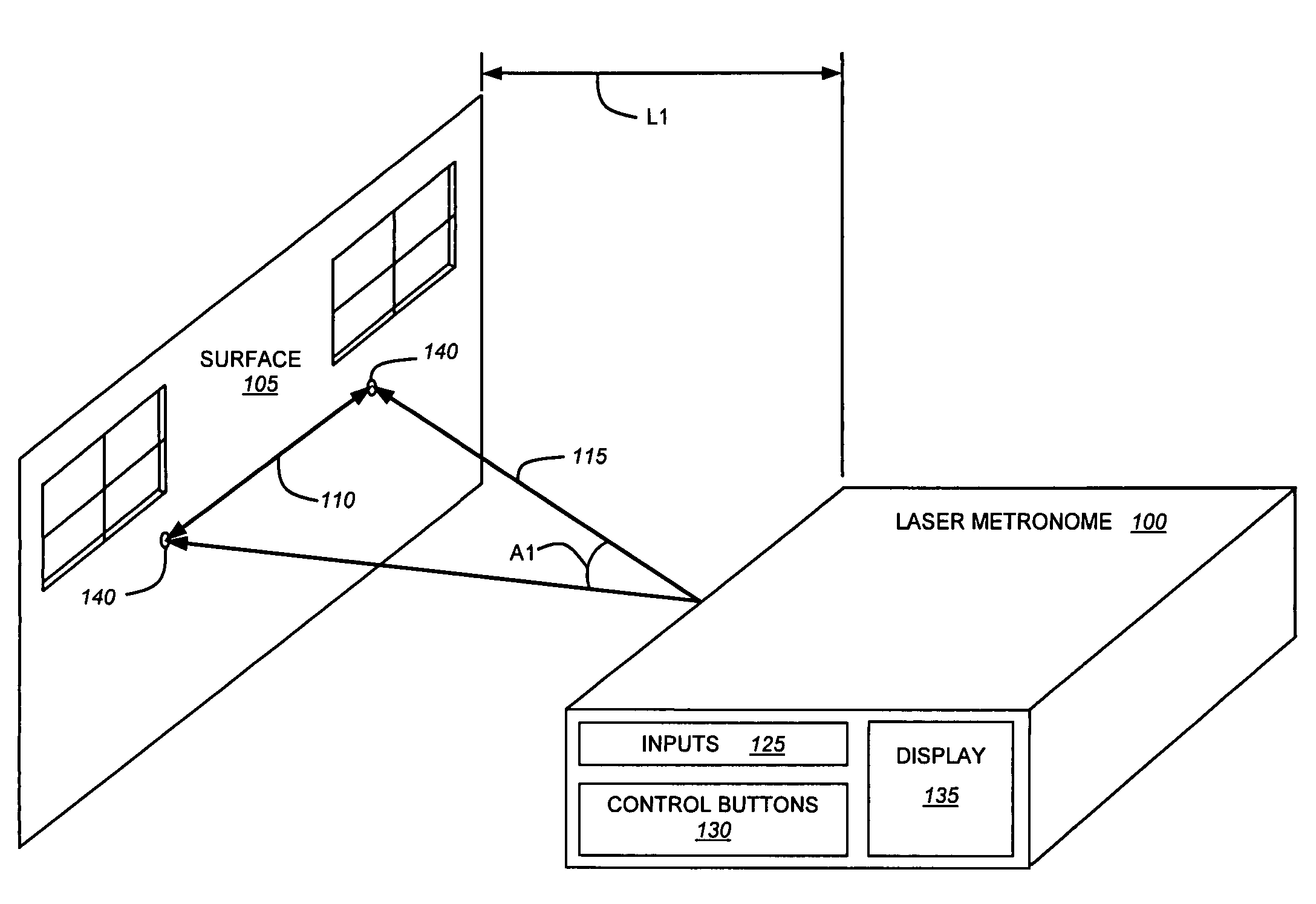
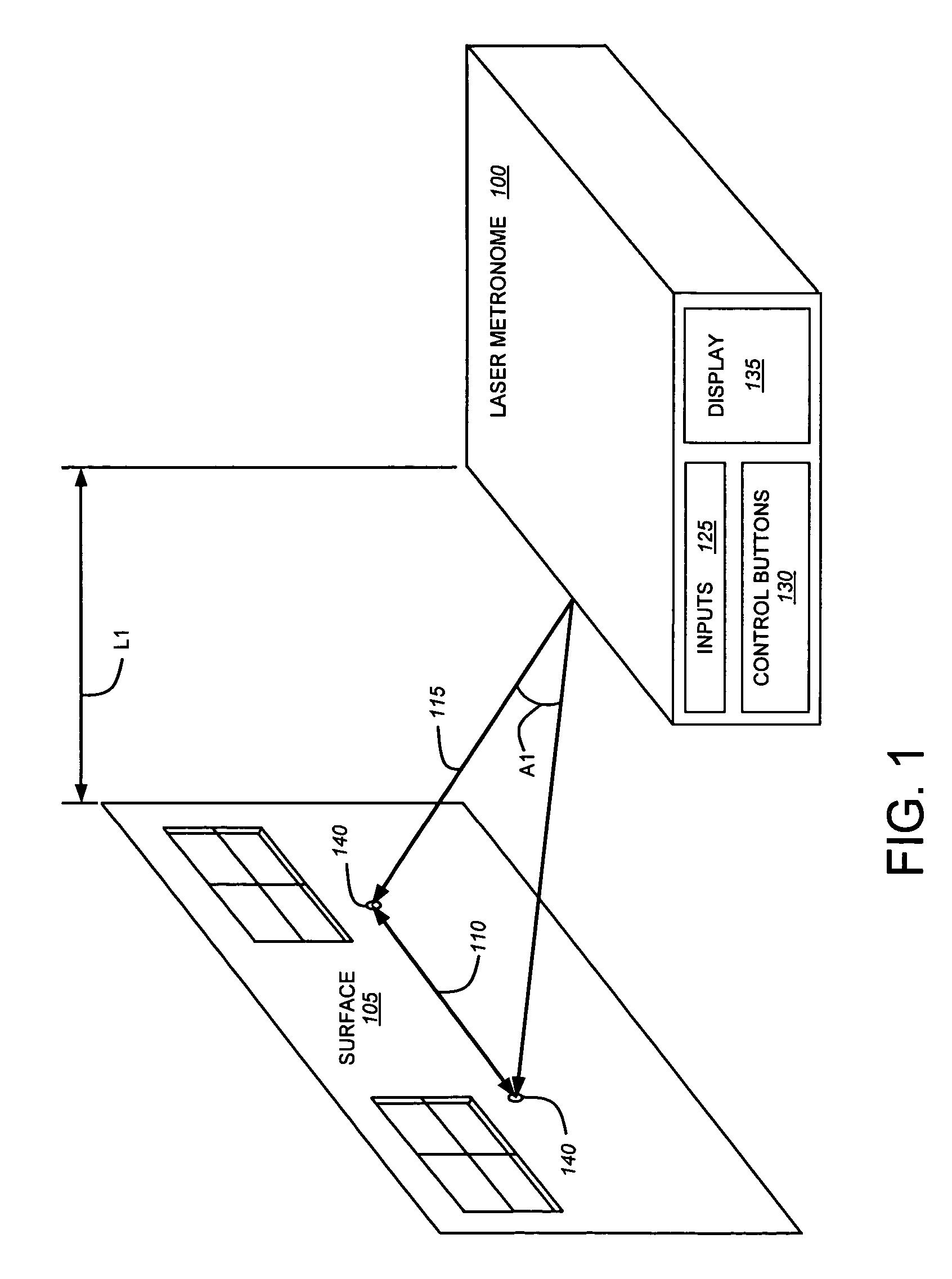
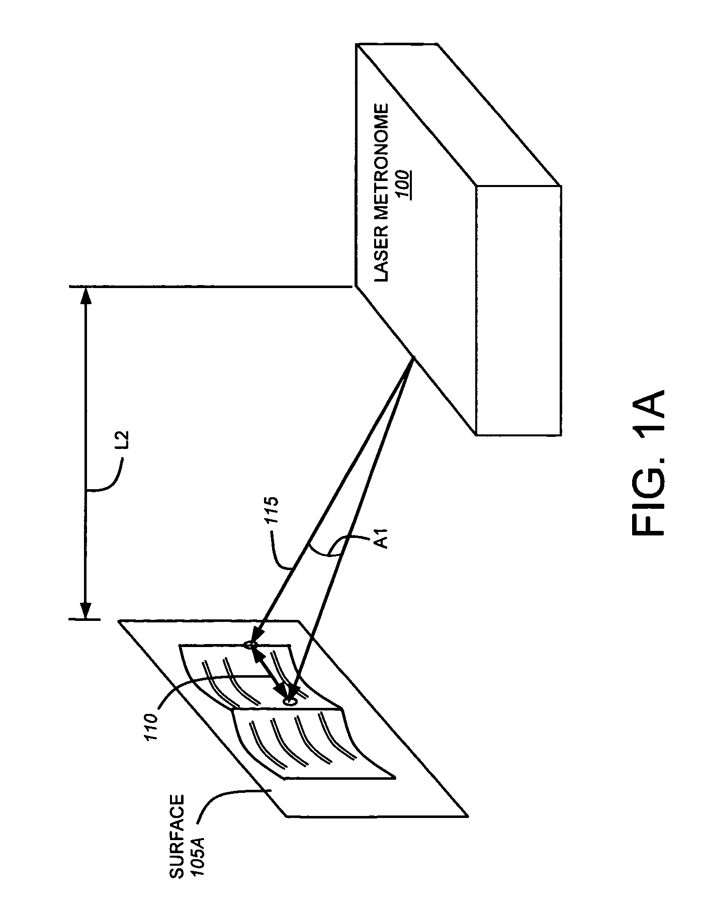
[0026]The present invention is directed to a system and method for projecting a visual queue to a conveniently viewable surface so as to indicate a tempo or a rhythm such that one or more musicians may be synchronized without requiring auditory interference, headphones, multiple devices, and / or a direct line of sight to the device. The present invention also provides a continuous visual indication of the progress of the tempo such that a musician may anticipate a beat.

[0027]Illustratively, a laser or other substantially collimated light source is operatively connected to a reciprocating driver that causes a beam from the laser to sweep back and forth across the conveniently viewable surface at an adjustable frequency, thereby tracing a path across the surface between two beam path boundaries. The beam's direction change at a beam path boundary generally serves as a visual indication of a new musical beat. The laser may be positioned and / or aimed to project the beam on any surface, i...


PUM


Abstract

A laser or other substantially collimated light source is operatively connected to a reciprocating driver that causes a beam from the laser to sweep across a conveniently viewable surface at an adjustable frequency, thereby tracing a pattern on the surface between a plurality of beam path boundaries. The beam's direction change at a beam path boundary generally serves as a visual indication of a musical beat. The laser may be positioned and / or aimed to project the beam on any surface. The frequency of driver reciprocation (i.e., the tempo) may be adjusted to correspond to one of a range of typical musical tempos, thereby providing the functionality of a metronome but with the novel and useful additional element of a projected beat image.

Description

CROSS-REFERENCE TO RELATED APPLICATION[0001]The present application claims the benefit of U.S. Provisional Patent Application Ser. No. 60 / 633,466, which was filed on Dec. 6, 2004, by Robert Lawliss et al. for a METRONOME WITH PROJECTED BEAT IMAGE and is hereby incorporated by reference.BACKGROUND OF THE INVENTION[0002]1. Field of the Invention[0003]The present invention relates to devices for indicating tempo or rhythm and, in particular, to metronomes using light.[0004]2. Background Information[0005]A metronome is a device that indicates a tempo or a rhythm. Musicians use metronomes when they practice or perform in order to keep a consistent tempo and / or to synchronize multiple musicians playing multiple musical instruments. A metronome may be adjusted to indicate any one of a range of tempos commonly used in musical compositions.[0006]Musicians have used traditional pendulum metronomes for centuries. A pendulum metronome is a mechanical device using a weight on a rod to control th...

Claims


Application Information

Patent Timeline
Patent Type & Authority Patents(United States)
IPC IPC(8): G09B15/00
CPCG04F5/025
Inventor LAWLISS, ROBERT W.BORNSTEIN, DAVID A.
Owner BORNSTEIN DAVID A
Why Eureka
Try Eureka