Operation control device for leg-type mobile robot and operation control method, and robot device

a mobile robot and operation control technology, applied in the direction of dynamo-electric converter control, distance measurement, instruments, etc., can solve the problems of tumbling that may critically damage the robot body itself or also damage a substance, and the robot body itself may be critically damaged or damaged

Active Publication Date: 2008-06-10
SONY CORP +1
View PDF26 Cites 66 Cited by
  • Summary
  • Abstract
  • Description
  • Claims
  • Application Information

AI Technical Summary

Benefits of technology

[0032]It is an object of the present invention to provide a superior legged mobile robot and a superior tumbling motion (fall down motion) controlling method for a legged mobile robot by which damage which may otherwise be given to the robot can be reduced as far as possible by motion control of an entire body including not only the leg parts but also the body and the arm parts during tumbling and dropping.
[0033]It is another object of the present invention to provide a superior motion controlling apparatus and motion controlling method for a legged mobile robot and a superior robot apparatus by which the robot can autonomously restore its standing posture from an on-floor posture such as a supine posture or a prone posture.
[0034]It is a further object of the present invention to provide a superior motion controlling apparatus and motion controlling method for a legged mobile robot and a superior robot apparatus by which the robot can restore its standing posture from an on-floor posture such as a supine posture or a prone posture through a stabilized motion with comparatively low torque.

Problems solved by technology

This is because tumbling of a robot signifies interruption of a work being performed and considerable labor and time are required until the robot stands up uprightly from the tumbling state and resumes the work.
Above all, there is the possibility that the tumbling may critically damage the robot body itself or also damage a substance with which the tumbling robot collides.
Accordingly, the problem of a posture variation caused by a variation of the road surface condition is significant particularly with a bipedal locomotion robot.
Naturally, the state of tumbling of a robot signifies interruption of a work being performed by the robot and considerable labor and time are required until the robot stands up uprightly from the tumbling state and resumes the work.
Further, there is the possibility that, above all, the tumbling may critically damage the robot body itself or also damage a substance with which the tumbling robot collides.
Although the possible best posture stabilization control is performed in order to prevent tumbling of a robot, the robot may still lose its stability in posture because of some defect in control, some unpredictable external factor (such as, for example, accidental collision with another substance, a road surface situation such as a projection or a depression on the floor, appearance of an obstacle or the like) to such a degree that it cannot be supported only with the movable legs thereof, resulting in tumbling.
Particularly in the case of a robot which performs bipedal legged traveling such as a human-type robot, since the position of the center of gravity is high and an uprightly standing stationary state itself of the robot is originally instable, the robot is likely to tumble.
If the robot tumbles, then there is the possibility that critical damage may be applied to the robot itself or to the other party side with which the robot collides by the tumbling.
However, even if power supply to the robot in such an on-floor posture as just described is made available, if the robot cannot stand up autonomously, then an operator must give a hand to lift the body, which is cumbersome to the operator.
However, the robot may sometimes tumble unfortunately.
Also in this instance, it still is cumbersome if an operator must give a hand to lift the body.
If the robot cannot stand up by itself every time it assumes an on-floor posture, then it cannot be operated in unmanned environments after all, and the operation lacks in self-conclusion.
Thus, the robot cannot be placed into fully self-contained environments.

Method used


Image

  • Operation control device for leg-type mobile robot and operation control method, and robot device
  • Operation control device for leg-type mobile robot and operation control method, and robot device
  • Operation control device for leg-type mobile robot and operation control method, and robot device

Examples


Embodiment Construction

[0150]In the following, an embodiment of the present invention is described in detail with reference to the drawings.

A. Mechanical Configuration of the Legged Mobile Robot

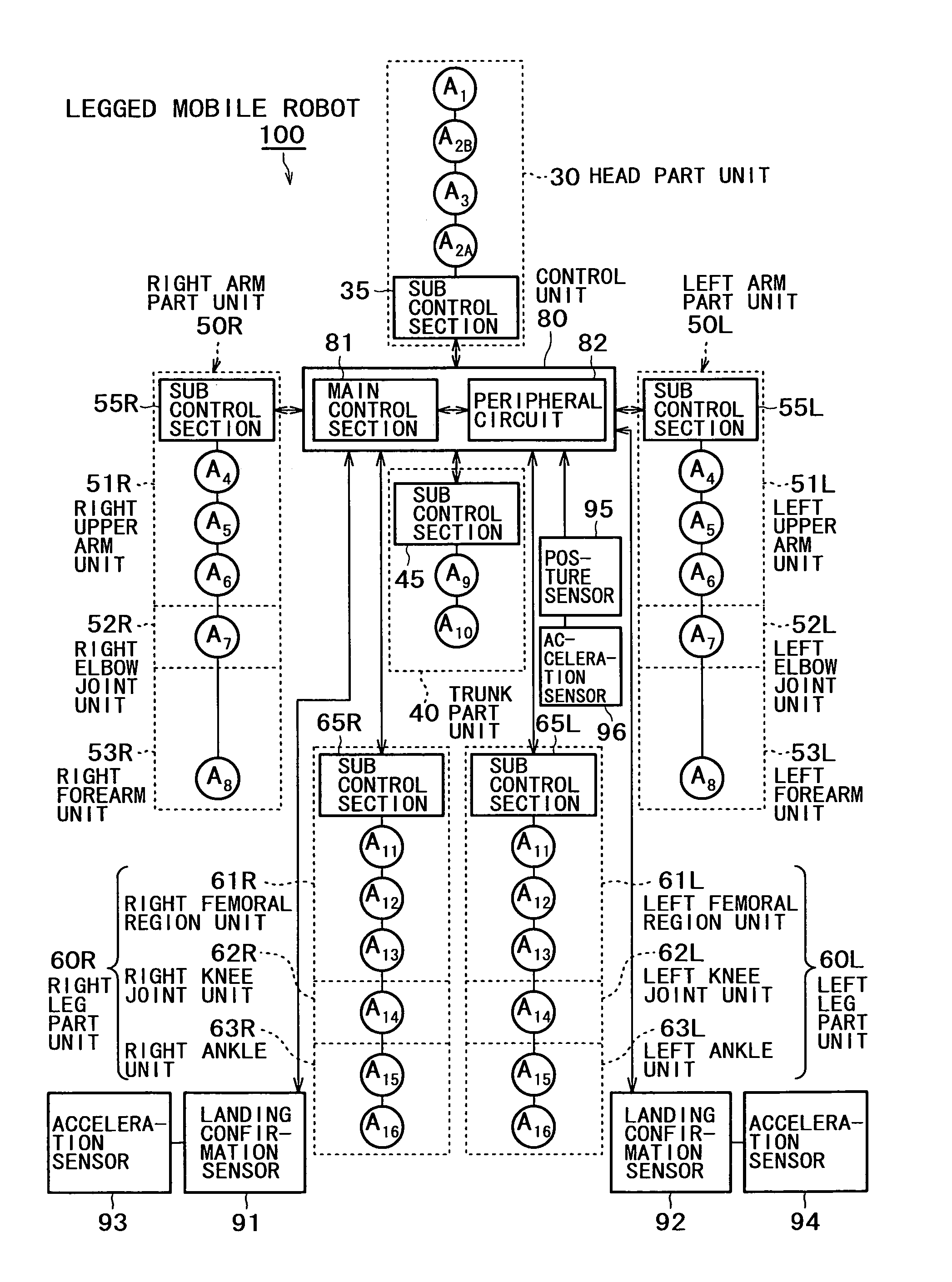
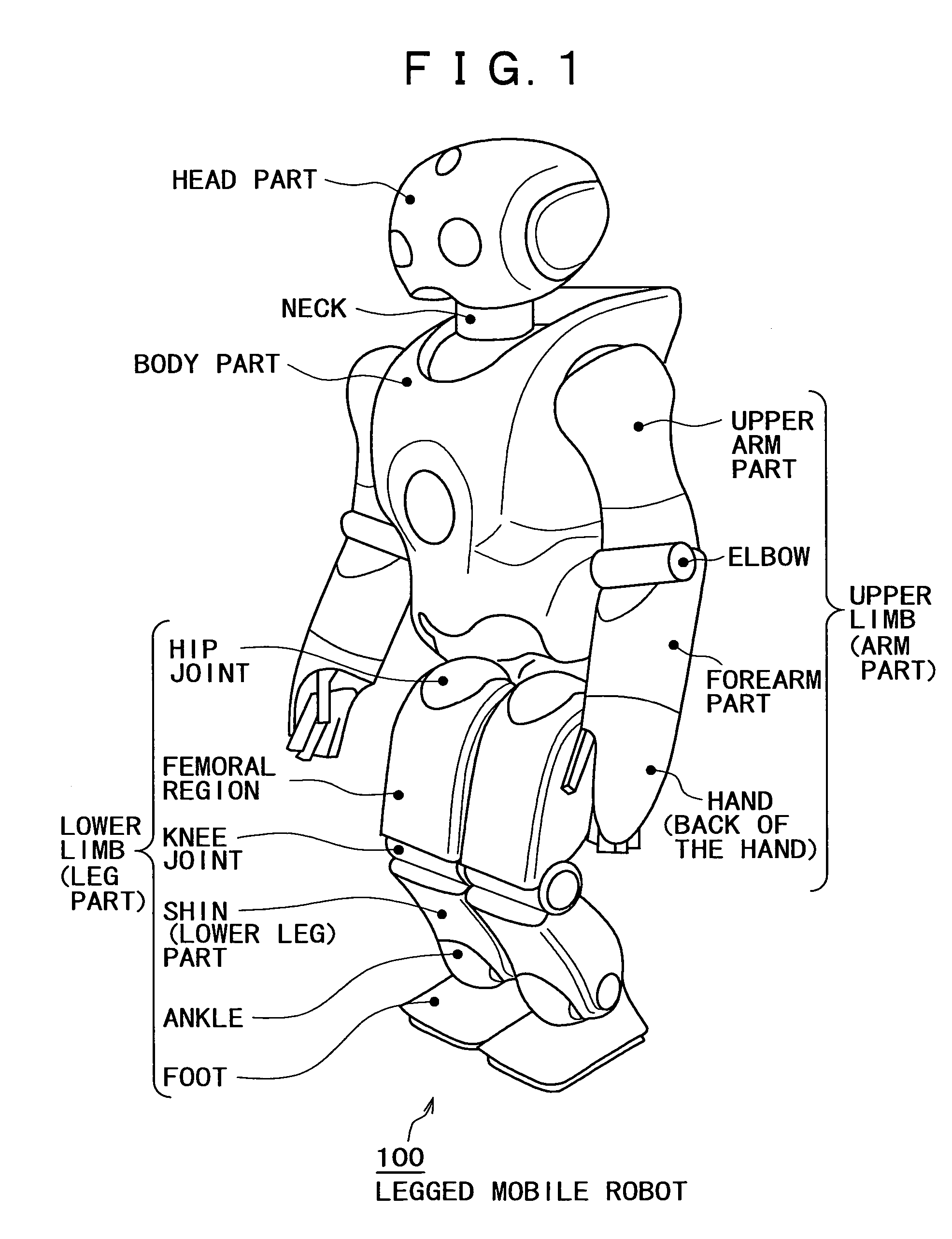
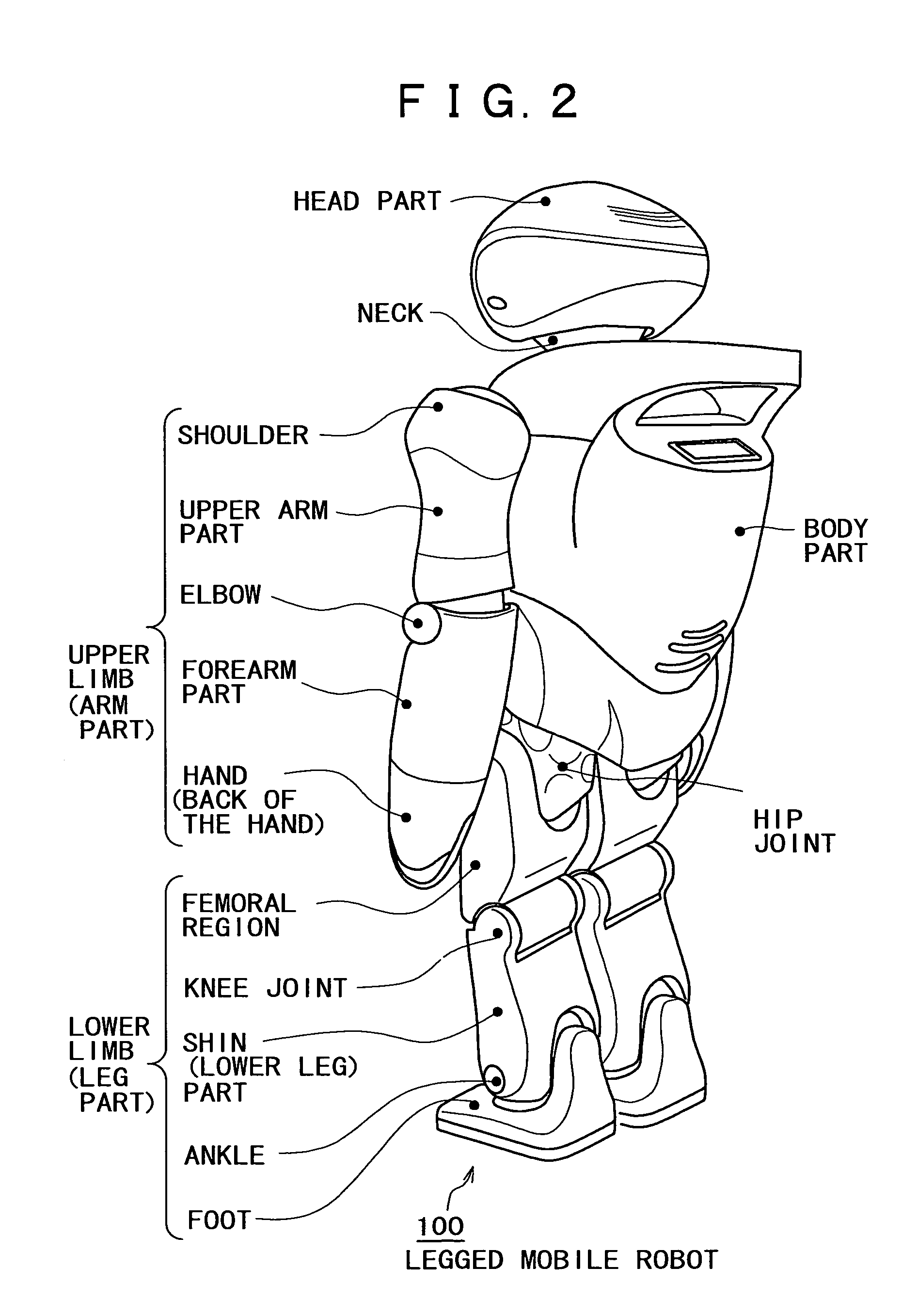
[0151]Referring to FIGS. 1 and 2, a “human-like” or “humanoid” legged mobile robot 100 to which the present invention is applied is shown in a manner wherein it stands uprightly as viewed from obliquely forward and obliquely rearward, respectively. As shown in FIGS. 1 and 2, the legged mobile robot 100 includes a body part, a head part, left and right upper limb parts, and left and right lower limb parts used for legged traveling. A control section (not shown) is built, for example, in the body part and generally controls action of the body.

[0152]Each of the left and right lower limb parts is composed of a femoral region, a knee joint, a shin part, an ankle and a foot and is connected to a substantially lowermost end of the trunk part by a hip joint. Meanwhile, each of the left and right upper limb parts is compose...


PUM


Abstract

A legged mobile robot gives up a normal walking motion and starts a tumbling motion when an excessively high external force or external moment is applied thereto and a behavior plan of a foot part thereof is disabled. At this time, the variation amount ΔS / Δt of the area S of a support polygon of the body per time t is minimized and the support polygon when the body drops onto a floor is maximized to distribute an impact which acts upon the body from the floor when the body drops onto the floor to the whole body to suppress the damage to the body to the minimum. Further, the legged mobile robot autonomously restores a standing up posture from an on-floor posture thereof such as a supine posture or a prone posture.

Description

TECHNICAL FIELD [0001]The present invention relates to a motion controlling apparatus and a motion controlling method for a legged mobile robot having a great number of joint degrees of freedom, and a robot apparatus, and more particularly to a motion controlling apparatus and a motion controlling method for a legged mobile robot which includes a plurality of movable legs and has a basic standing posture, and a robot apparatus.[0002]More specifically, the present invention relates to a motion controlling apparatus and a motion controlling method for a legged mobile robot wherein a ZMP (Zero Moment Point) is used as a posture stability determination criterion to stabilize and control the position of the body during movement, and more particularly to a motion controlling apparatus and a motion controlling method for a legged mobile robot wherein the damage which may otherwise be given to the robot is reduced as far as possible by motion control of the entire body during tumbling (fall...

Claims


Application Information

Patent Timeline
Patent Type & Authority Patents(United States)
IPC IPC(8): G06F19/00B62D57/02B62D57/032
CPCB62D57/02B62D57/032B25J5/00B25J13/00
Inventor MIKAMI, TATSUOYAMAGUCHI, JINICHIMIYAMOTO, ATSUSHI
Owner SONY CORP
Why Eureka
Try Eureka