
Method of forming cascaded stator winding

a cascaded, stator technology, applied in the field of electric machines, can solve the problems of increasing the complexity of winding the stator, disadvantages of the stator,

Active Publication Date: 2008-06-17
REMY TECHNOLOGIES LLC
View PDF120 Cites 32 Cited by
  • Summary
  • Abstract
  • Description
  • Claims
  • Application Information

AI Technical Summary

Benefits of technology

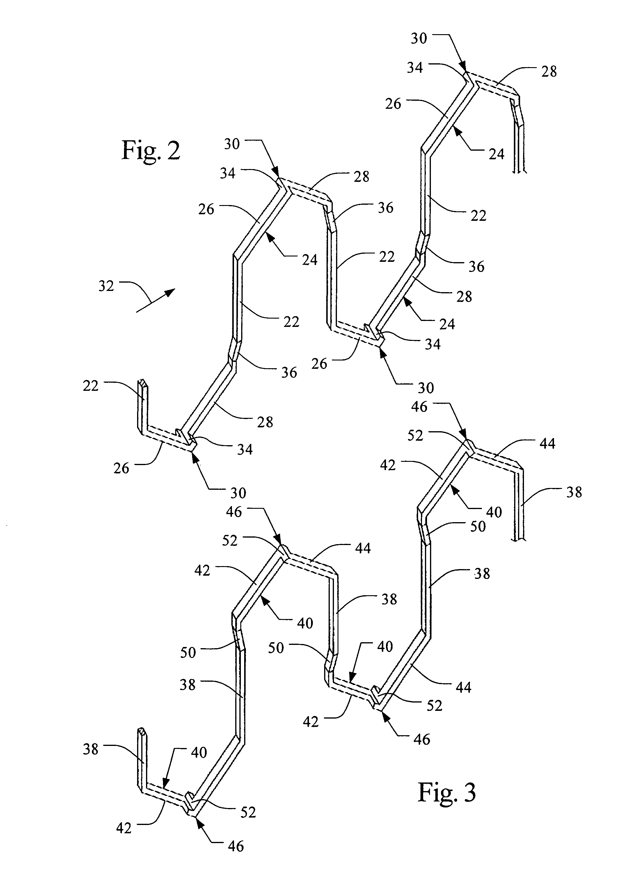
"The present patent application describes a method for forming a cascaded stator winding, which is simpler and more efficient than the interlaced winding process of the prior art. The stator winding is cascaded and not interlaced, meaning that the slot segments of a conductor do not alternate with other conductors. The end loop segments of the conductors are formed such that they are radially aligned in each layer, allowing for the conductors to be inserted into the stator core in a radially aligned manner. This method simplifies the process of forming a stator winding and improves the efficiency of the stator's performance."

Problems solved by technology

These stators, however, are disadvantageous because the windings are typically interlaced, in which the wires are required to alternate outer and inner radial portions of each slot.
These interlaced windings require an interlacing process to interlace the conductors of all the phases prior to inserting the winding into the core and therefore disadvantageously increase the complexity of placing the winding the stator.

Method used


Image

  • Method of forming cascaded stator winding
  • Method of forming cascaded stator winding
  • Method of forming cascaded stator winding

Examples


Embodiment Construction

[0020]A stator core having a cascaded winding is described in patent application Ser. No. 10 / 443,441, filed on May 22, 2003, which is assigned to the assignee of the present application and is hereby incorporated by reference into the present application.

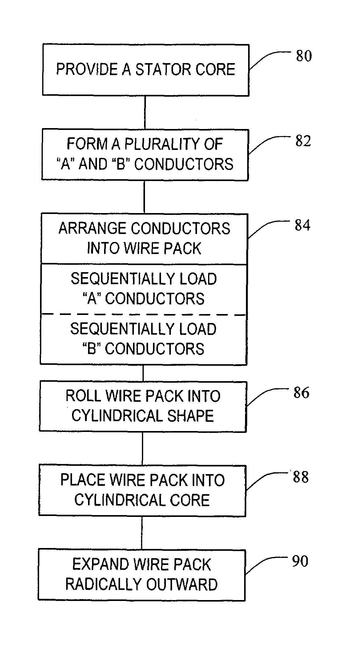
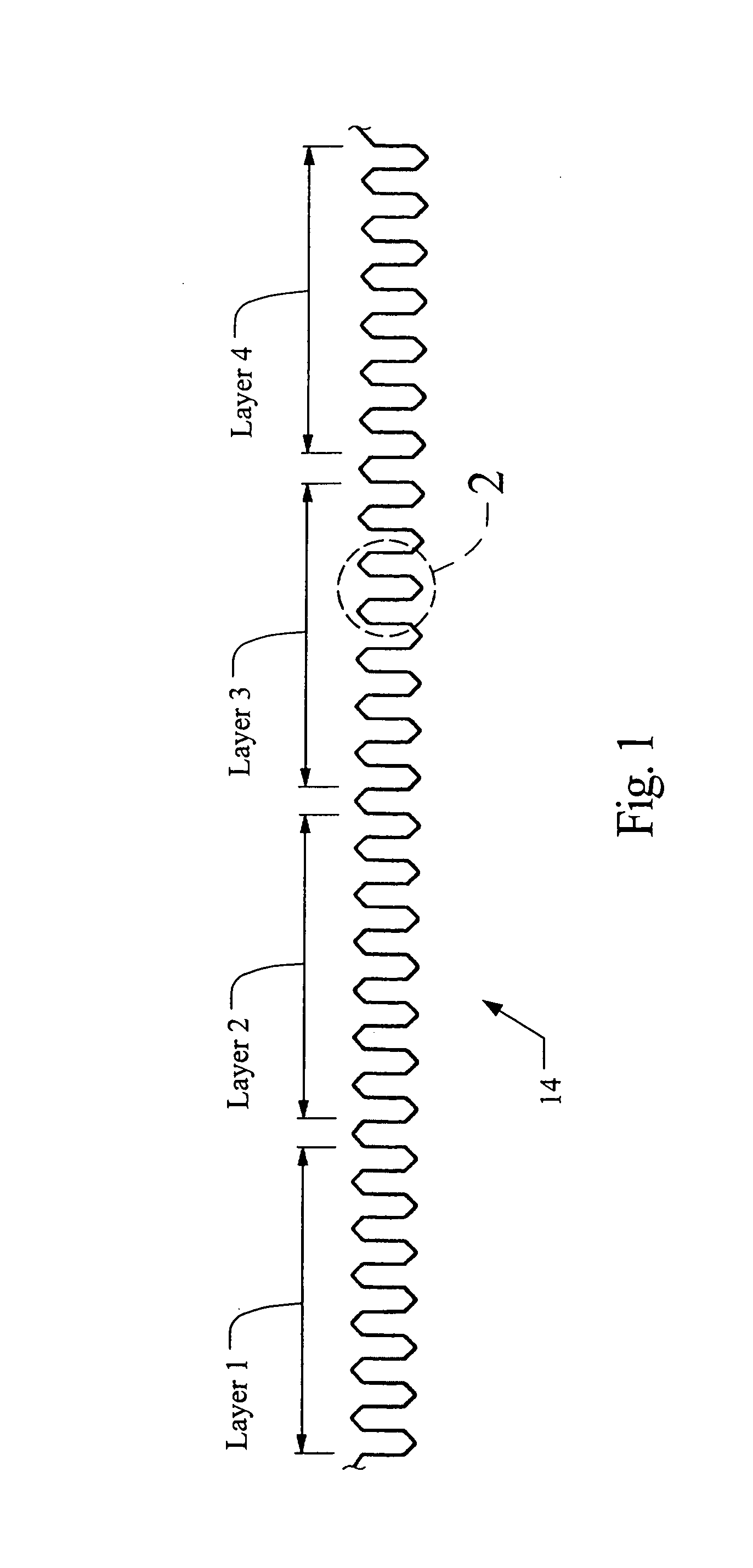
[0021]As seen in FIG. 11, a method of forming a stator core having a cascaded stator winding includes the steps of: providing a stator core 10 having a plurality of circumferentially spaced and axially-extending core slots 12 formed therein (box 80), forming a plurality of A conductors 14, forming a plurality of B conductors 16 (box 82), arranging the A and B conductors 14,16 into a wire pack 18 (box 84), rolling the wire pack 18 into a cylindrical shape (box 86), placing the wire pack 18 within the stator core 10 (box 88), and expanding the wire pack 18 radially outward such that the wire pack 18 is inserted within the slots 12 of the stator core 10 (box 90).

[0022]Each of the A and B conductors 14, 16 may be formed from a single co...


PUM

PropertyMeasurementUnit
shapeaaaaaaaaaa
outer dimensionaaaaaaaaaa
circumferential widthaaaaaaaaaa

Abstract

A method of forming a stator for an electric machine having a cascaded winding includes the steps of: providing a stator core having a plurality of circumferentially spaced and axially-extending core slots in a surface thereof, forming a plurality of A conductors and a plurality of B conductors, arranging the A and B conductors into a wire pack, rolling the wire pack into a cylindrical shape and inserting the wire pack within the stator core, and expanding the wire pack radially outward such that the wire pack is inserted within the slots of the stator core.

Description

BACKGROUND OF THE INVENTION[0001]The present invention relates generally to electric machines and, in particular, to a stator winding for an electric machine having cascaded end loops. Electric machines, such as alternating current electric generators, or alternators are well known. Prior art alternators typically include a stator assembly and a rotor assembly disposed in an alternator housing. The stator assembly is mounted to the housing and includes a generally cylindrically-shaped stator core having a plurality of slots formed therein. The rotor assembly includes a motor rotor attached to a generally cylindrical shaft that is rotatably mounted in the housing and is coaxial with the stator assembly. The stator assembly includes a plurality of wires wound thereon, forming windings. The stator windings are formed of slot segments that are located in the slots and end loop sections that connect two adjacent slot segments of a conductor of each phase and are formed in a predetermined...

Claims


Application Information

Patent Timeline
Patent Type & Authority Patents(United States)
IPC IPC(8): H02K15/00
CPCH02K15/0435H02K15/06Y10T29/49009Y10T29/49011Y10T29/49012Y10T29/49073H02K15/0478
Inventor NEET, KIRK E.BRAMSON, ERIC DAVID
Owner REMY TECHNOLOGIES LLC
Learn More