Gas powered toy gun

a toy gun and gas technology, applied in the field of gas powered toy guns, can solve the problems of excessive mechanical shock, disadvantages or problems on the backward movement of the slider, and the body of the gas powered toy gun is destroyed

Inactive Publication Date: 2008-06-17
WESTERN ARMS
View PDF27 Cites 16 Cited by
  • Summary
  • Abstract
  • Description
  • Claims
  • Application Information

AI Technical Summary

Benefits of technology

[0009]Another object of the present invention is to provide a gas powered toy gun, in which the shooting of a sham bullet put in a bullet holding chamber and the movement of a slider for supplying the bullet holding chamber which has been made empty with the next sham bullet are carried out by means of pressure of gas, and the pressure of gas used for moving the slider backward is maintained to have a pressure value for causing the slider to move at an appropriate speed regardless of variations in atmospheric temperature.

Problems solved by technology

However, in order to attach great importance to easy handling, safety and so on, the gas used for the gas powered toy gun is usually selected to be low-pressure liquefied gas which varies in its pressure on a relatively large scale in response to temperature variations, and therefore it is feared that disadvantages or problems on the backward movement of the slider are brought about with variations in atmospheric temperature.
For example, in a season of relatively high atmospheric temperature, the pressure of gas used for moving the slider backward has such a high pressure value as to causing the slider to move at an extremely high speed toward the most retreated position and, as a result, an excessive mechanical shock is caused when the slider reaches to the most retreated position.
In this case, it is feared that a body of the gas powered toy gun is destroyed with repetition of such excessive mechanical shock as mentioned above.
Further, in a season of relatively low atmospheric temperature, the pressure of gas used for moving the slider backward has such a low pressure value as to be insufficient for causing the slider to reach to the most retreated position and, as a result, it is feared that the movable member can not move appropriately.
However, any previously proposed gas powered toy gun arranged to meet the requirement has not been found.

Method used


Image

  • Gas powered toy gun
  • Gas powered toy gun
  • Gas powered toy gun

Examples


first embodiment

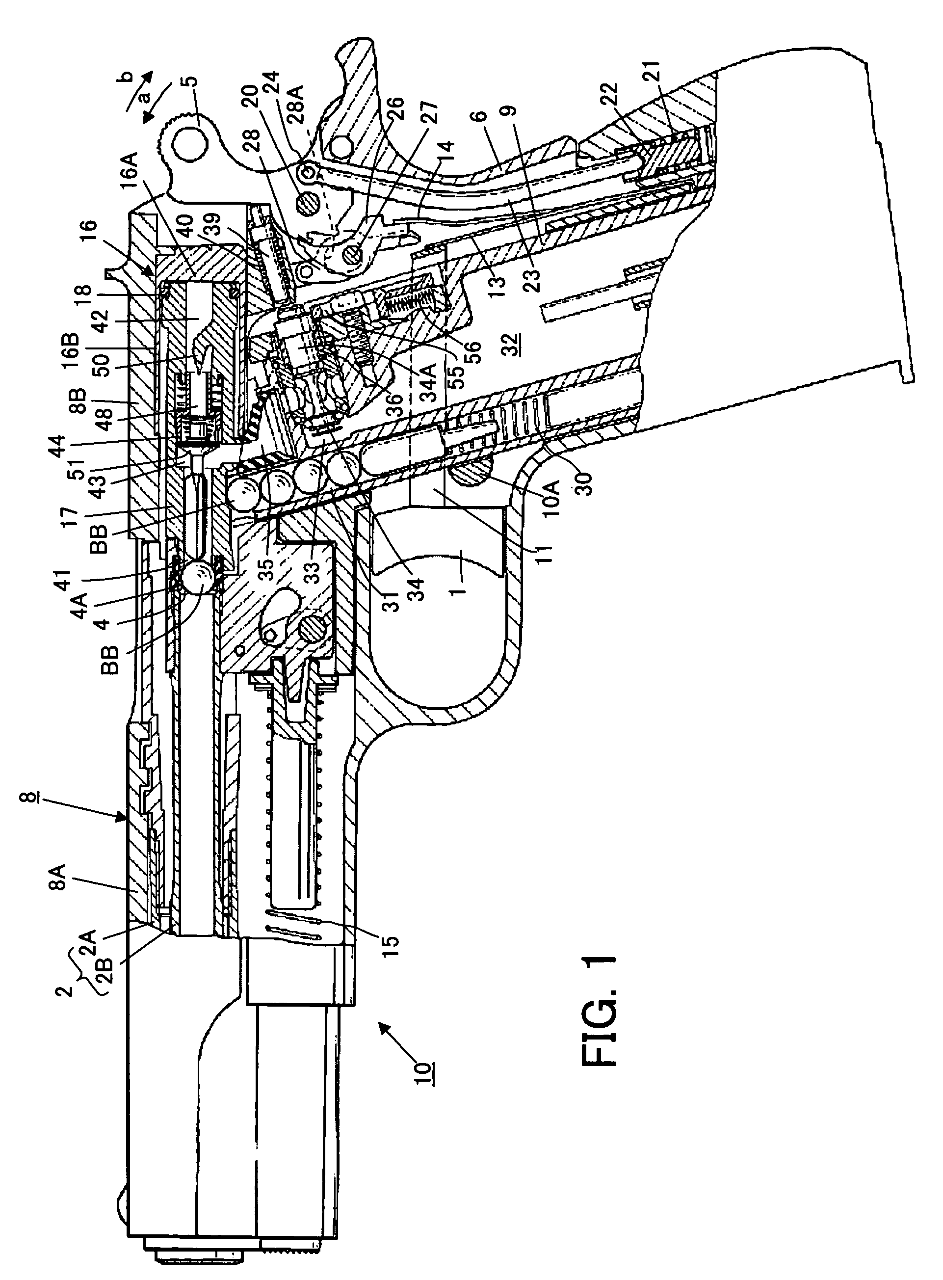
[0021]FIG. 1 shows gas powered toy gun according to the present invention.

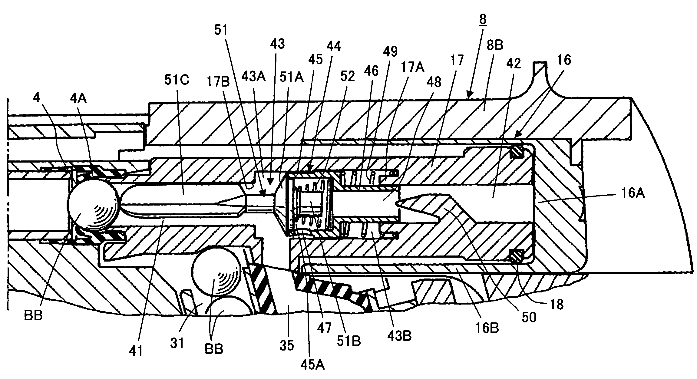
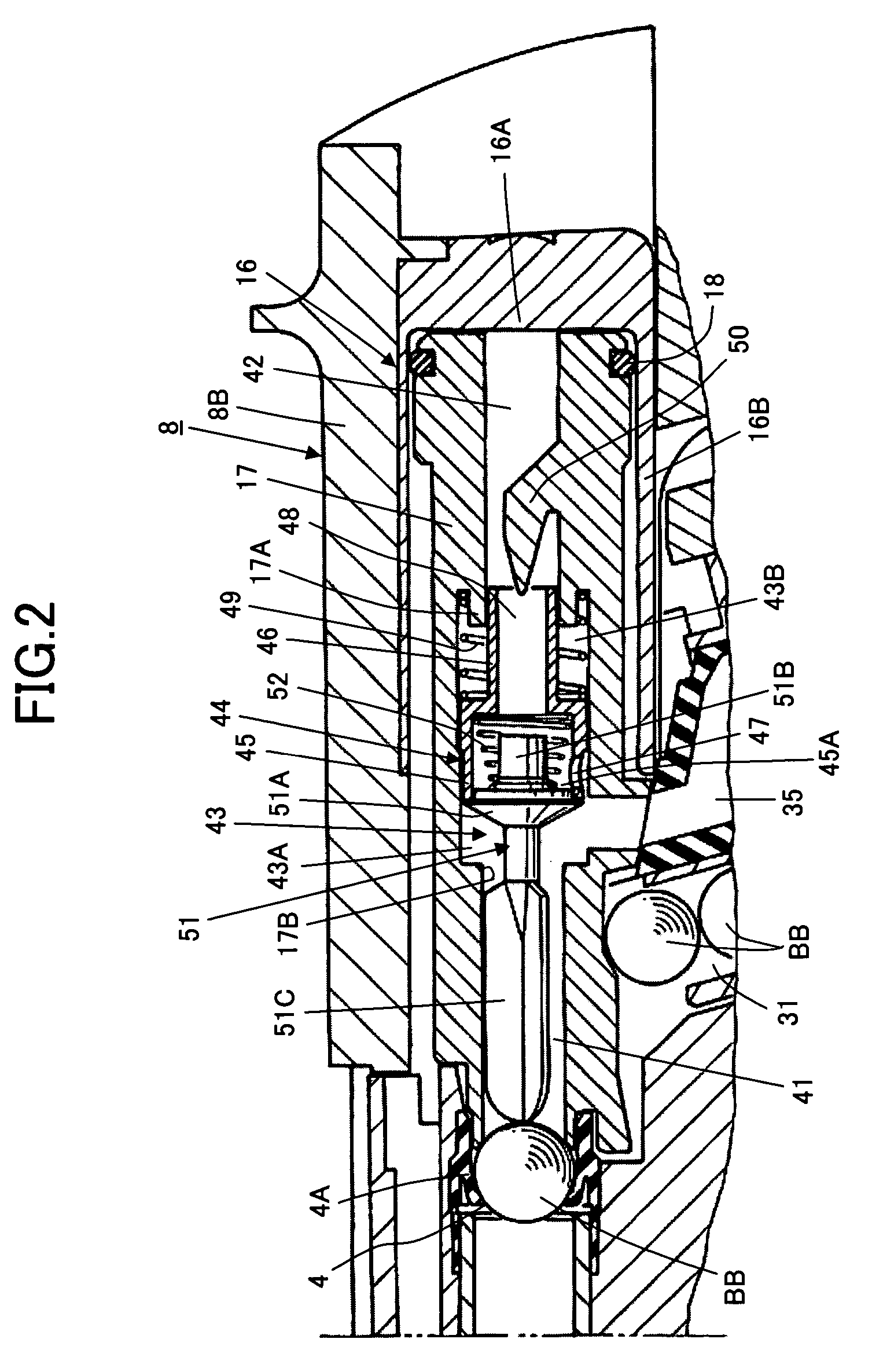
[0022]Referring to FIG. 1, the first embodiment of gas powered toy gun according to the present invention has a body 10 in which a trigger 1, a barrel portion 2 constituted with an outer barrel 2A and an inner barrel 2B, a bullet holding chamber 4, a hammer 5 and a grip 6 are provided, a case 9 held to be detachable in the grip 6, and a slider 8 provided to be movable along the barrel portion 2. For the sake of convenience in explanation, hereinafter, a side of a muzzle provided on the barrel portion 2 of the first embodiment shown in FIG. 1 is referred to a front or forward side and a side of the hammer 5 of the first embodiment shown in FIG. 1 is referred to a rear or backward side. For example, the bullet holding chamber 4 is positioned on a rear end of the barrel portion 2 and the slider 8 is able to move forward and backward along the barrel portion 2.

[0023]The bullet holding chamber 4 positioned on the r...

second embodiment

[0072]FIG. 14 shows gas powered toy gun according to the present invention.

[0073]The second embodiment shown in FIG. 14 corresponds to a modification of the first embodiment shown in FIGS. 1 and 2, in which a fixed member 70 is provided instead of the fixed member 50 constituting, together with the gas flow limiting member 44, the gas flow adjusting mechanism in the first embodiment. In FIG. 14, various portions and members corresponding to those in the first embodiment shown in FIGS. 1 and 2 are marked with the same references and further description thereof will be omitted.

[0074]Referring to FIG. 14, the fixed member 70 is incorporated with a movable member 17 to be positioned behind a gas flow limiting member 44 in the movable member 17. The fixed member 70 is shaped into a plate planted in the movable member 17 to form a wall opposite to a rear end of a cylindrical portion 46 of the gas flow limiting member 44 (an opening of a third gas passage 48). A gas passage through which g...

third embodiment

[0091]FIG. 17 shows gas powered toy gun according to the present invention.

[0092]The third embodiment shown in FIG. 17 corresponds to a modification of the first embodiment shown in FIGS. 1 and 2, in which a bottomless cup-shaped portion 17C having an opening 75 is provided on a movable member 17 instead of the circular contacting portion 17A provided on the movable member 17 in the first embodiment and a gas flow adjusting mechanism including a movable gas passage controlling member 76 is provided instead of the gas flow adjusting mechanism constituted with the gas flow limiting member 44 and the fixed member 50 in the first embodiment.

[0093]In FIG. 17, various portions and members corresponding to those in the first embodiment shown in FIGS. 1 and 2 are marked with the same references and further description thereof will be omitted.

[0094]Referring to FIG. 14, in an inner space formed in the movable member 17, a coil spring 52 operative to force a gas passage controller 51 to be pu...


PUM


Abstract

A gas powered toy gun comprises a gas supplying portion from which a gas leading passage extends, a valve for controlling the gas leading passage to be open and closed selectively, a slider provided to be movable to a barrel portion connected with a bullet holding chamber and provided with a pressure receiving portion for moving backward in order to supply the bullet holding chamber with a sham bullet, a movable member having an inner space formed therein and provided to be movable in the slider so as to be put selectively in a first state wherein the inner space is coupled with the gas leading passage and in a second state wherein the inner space is removed from the gas leading passage for guiding gas flowing through the gas leading passage to the bullet holding chamber through the inner space so that the sham bullet put in the bullet holding chamber is shot with pressure of gas acting thereon and for guiding further the gas flowing through the gas leading passage to the pressure receiving portion through the inner space so that the slider is moved backward with pressure of gas acting on the pressure receiving portion, and gas flow adjusting means provided in the inner space formed in the movable member for adjusting the amount of gas flowing through the inner space to the pressure receiving portion in response to pressure of gas led into the inner space.

Description

BACKGROUND OF THE INVENTION[0001]1. Field of the Invention[0002]The present invention relates generally to a gas powered toy gun, and more particularly to an improvement in a toy gun, in which the shooting of a sham bullet put in a bullet holding chamber and the backward movement of a slider for supplying the bullet holding chamber with the next sham bullet are carried out by means of pressure of gas.[0003]2. Description of the Prior Art[0004]A toy gun which utilizes gas pressure, namely, pressure brought about by air or gas other than air is usually made to imitate a real gun in not only its color and shape but also its apparent operations. As one of these toy guns utilizing gas pressure, it has been proposed a gas powered toy gun in which a pressure accumulating chamber is formed in a grip to be filled with compressed gas and a gas passage extending from the pressure accumulating chamber is opened, by means of the rotation of a hammer linked with a trigger to operate in response t...

Claims


Application Information

Patent Timeline
Patent Type & Authority Patents(United States)
IPC IPC(8): F41B11/32F41B11/68F41B11/56F41B11/62F41B11/723
CPCF41B11/721F41B11/62F41B11/64F41B11/89
Inventor KUNIMOTO, KENICHI
Owner WESTERN ARMS
Why Eureka
Try Eureka