Clutch control device for work machine

a technology of work machine and control device, which is applied in the direction of temperature control using plurality of sensors, clutches, engine cooling apparatus, etc., can solve the problems of torque loss and difficulty in controlling the rotational speed of the fan to the desired rotational speed

Active Publication Date: 2018-03-29
NIHON KENKI CO LTD
View PDF0 Cites 8 Cited by
  • Summary
  • Abstract
  • Description
  • Claims
  • Application Information

AI Technical Summary

Benefits of technology

[0007]With the configuration described above of the present invention, it becomes possible to provide the clutch control device for the work machine capable of controlling the rotational speed of the fan to an appropriate rotational speed. Incidentally, other objects, configurations and advantageous effects than those as aforementioned will be clarified by the description of the following embodiments.
than those as aforementioned will be clarified by the description of the following embodiments.

Problems solved by technology

Thus, in the wet friction clutches, a torque loss, a so-called drag torque attributed to the viscosity of the oil is generated even during the idling of the clutch.
Accordingly, in approximating the rotational speed of a fan driven by an engine to a target rotational speed, there arises a problem that the response is delayed if consideration is not taken into a change in the clutch characteristic, so that it is difficult to control the rotational speed of the fan to a desired rotational speed.

Method used


Image

  • Clutch control device for work machine
  • Clutch control device for work machine
  • Clutch control device for work machine

Examples


first embodiment

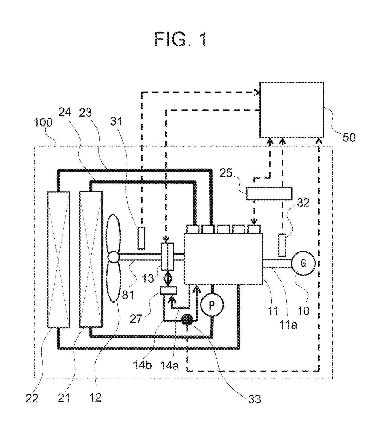
[0026]FIG. 1 is an illustration showing the overall configuration in an engine room of a work machine to which a clutch control device according to the present invention is applied. Although the clutch control device according to the present invention is applicable to various work machines such as a hydraulic excavator, a wheel loader, a dump track and the like, the following description will be made taking an example in which the present invention is applied to a hydraulic excavator.

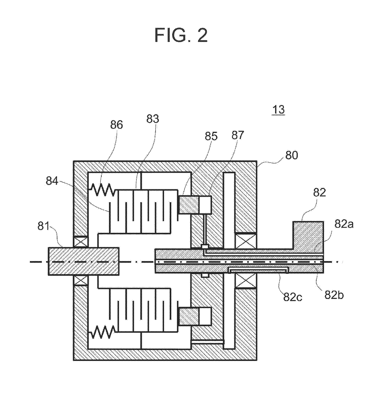
[0027]As shown in FIG. 1, an engine 11 as a prime mover is arranged in an engine room 100, and the engine 11 is connected to various devices such as, for example, a generator 10 through a drive shaft 11a. Further, an engine controller 25 is mounted on the engine 11, and the engine controller 25 executes monitoring the condition of the engine 11, adjusting the injection quantity of fuel in correspondence to a rotational speed command, and the like. Further, the engine 11 is connected through a pipe 24 to...

second embodiment

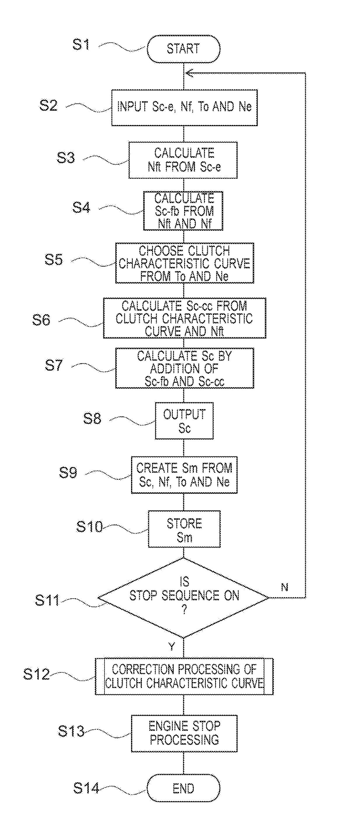
[0058]Next, description will be made regarding a clutch control device according to a second embodiment of the present invention. FIG. 10 is a function block diagram showing an internal configuration of the controller 50 in the clutch control device according to the second embodiment. As shown in FIG. 10, the principal feature of the second embodiment resides in that the controller 50 is configured to further include an oil deterioration judging module 62b for judging the deterioration of the engine oil and a clutch characteristic curve correction module 63 for correcting the clutch characteristic curve. Therefore, the following description will be made mainly regarding these featured portions, while description will be omitted about the configurations that are the same or identical with those in the foregoing first embodiment.

[0059]As shown in FIG. 10, the clutch characteristic curve correction module 63 receives the actual fan rotational speed Nf, the clutch oil temperature To, th...


PUM


Abstract

Provided is a clutch control device for a work machine capable of controlling a fan to an appropriate rotational speed. In the clutch control device for the work machine, a controller includes a target fan rotational speed calculation module that calculates a target fan rotational speed for the fan, a clutch characteristic curve storage module that stores a plurality of clutch characteristic curves, a clutch command calculation module that outputs with reference to a clutch characteristic curve a first clutch control signal corresponding to the target fan rotational speed, a feedback control module that output a second clutch control signal based on the difference between the target fan rotational speed and an actual fan rotational speed, and an adder that adds the first clutch control signal and the second clutch control signal to output a third clutch control signal.

Description

BACKGROUND1. Field of the Invention[0001]The present invention relates to a clutch control device for a work machine.2. Description of the Related Art[0002]As a background art in the present technical field, for example, Japanese Unexamined Patent Application Publication No. H4-296227 describes a configuration wherein “a slip control device is provided with a clutch characteristic curve memory, this memory stores position target signals in the form of a characteristic curve in dependence on data, the data representing rotational torques to be transmitted by a clutch at the target positions, the clutch characteristic curve memory outputs a position target signal in correspondence to an instantaneous rotational torque of an engine detected by a rotational torque detector, and the slip control device superposes the position target signal from the clutch characteristic curve memory on a control signal component generated by a controller of the slip control device” (refer to abstract).[0...

Claims


Application Information

Patent Timeline
Patent Type & Authority Applications(United States)
IPC IPC(8): F16D48/06
CPCF16D48/06F16D2500/3067F16D2500/7101F16D2500/7061F16D2500/70446F16D2500/3056F01P5/02F16D48/064G05D23/1927F16D2500/30426F16D2500/70442
Inventor FUKUDA, NAOKIOSAKA, TADASHIKOUNO, RYUJIARAI, MASATSUGUIKARI, TAKANOBUTANAKA, TAKAAKI
Owner NIHON KENKI CO LTD
Why Eureka
Try Eureka