System and method for performing directed self-assembly in a 3-D virtual fabrication environment

a technology of virtual fabrication environment and directed self-assembly, which is applied in the direction of computer control, program control, instruments, etc., can solve the problems of long experimental run duration, negative or null characterization, and high cost, and achieve the effect of reducing the cost of production, and improving the quality of production

Active Publication Date: 2018-05-08
COVENTOR
View PDF10 Cites 8 Cited by
  • Summary
  • Abstract
  • Description
  • Claims
  • Application Information

AI Technical Summary

Benefits of technology

[0006]Embodiments of the present invention enable the modeling of a DSA step within a virtual fabrication process sequence for a semiconductor device structure. A 3D model is created through virtual fabrication that represents and depicts the possible variation that can result from applying the DSA step as part of the larger fabrication sequence for the semiconductor device structure of interest. Embodiments capture the relevant behavior of polymer segregation into separate domains thereby allowing the modeling of the DSA step to take place with a speed appropriate for a virtual fabrication flow.

Problems solved by technology

Due to the increasing complexity of advanced technology node process flows, a large portion of the experimental fabrication runs result in negative or null characterization results.
These experimental runs are long in duration, weeks to months in the “fab” (fabrication environment), and expensive, as each experimental wafer may cost $3,000-$10,000.
Recent semiconductor technology advances, including FinFET, TriGate, High-K / Metal-Gate, embedded memories and advanced patterning, have dramatically increased the complexity of integrated semiconductor fabrication processes.
The cost and duration of technology development using this trial-and-error experimental methodology has concurrently increased.
General-purpose mechanical CAD tools have been found inadequate because they do not automatically mimic the material addition, removal, and modification processes that occur in an actual fab.
Furthermore because of the amount of data and computations required for physics-based simulations of processes, TCAD simulations are practically restricted to very small regions on a chip, most often encompassing just a single transistor.
In state-of-the-art semiconductor fabrication technologies, most of the integration challenge concerns the interaction between processes that may be widely separated in the integrated process flow and the multiple different devices and circuits that comprise a full technology suite (transistors, resistors, capacitors, memories, etc.).
Structural failures, stemming from both systematic and random effects, are typically the limiter in time-to-market for a new process technology node.

Method used


Image

  • System and method for performing directed self-assembly in a 3-D virtual fabrication environment
  • System and method for performing directed self-assembly in a 3-D virtual fabrication environment
  • System and method for performing directed self-assembly in a 3-D virtual fabrication environment

Examples


Embodiment Construction

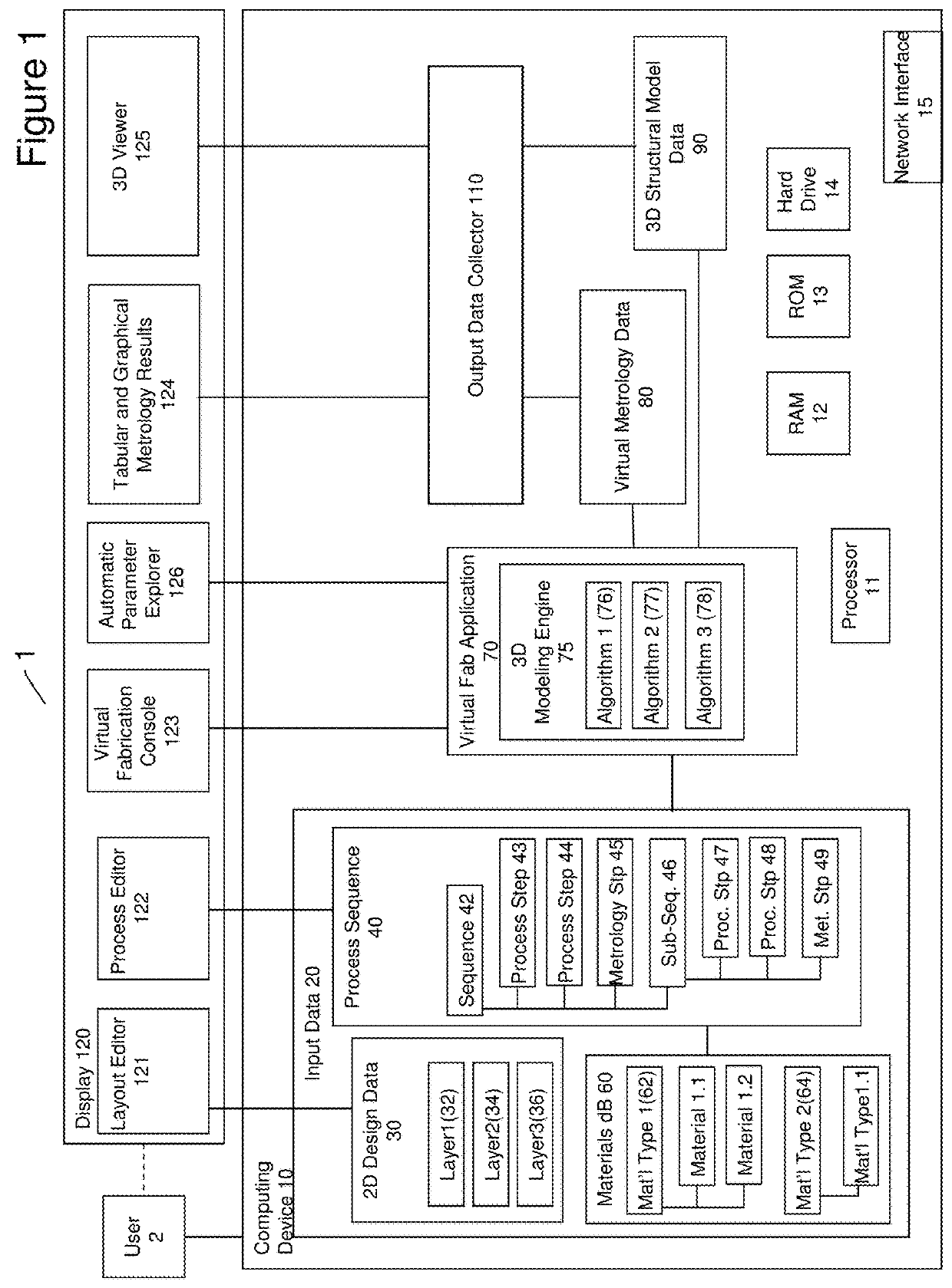
[0045]In one embodiment, a faster and more economical approach to semiconductor device structure development is provided. By enhancing a virtual fabrication environment to include the use of virtual metrology measurement data, the effect of alterations in a process or process sequence on device structure can be determined, leading to an optimized fabrication sequence. Further, by calibrating the virtual fabrication environment by comparing virtual metrology data generated from a virtual fabrication run with a subset of measurements performed in a physical fabrication environment, the virtual fabrication environment of the present invention becomes increasingly physically predictive when generating model device structures. Additionally, by conducting virtual experiments in the virtual fabrication environment of the present invention, multiple device structure models may be generated using ranges of process parameters and design parameter variations to cover an entire process and desi...


PUM

PropertyMeasurementUnit
heightaaaaaaaaaa
angleaaaaaaaaaa
morphologyaaaaaaaaaa

Abstract

The modeling of a DSA step within a virtual fabrication process sequence for a semiconductor device structure is discussed. A 3D model is created by the virtual fabrication that represents and depicts the possible variation that can result from applying the DSA step as part of the larger fabrication sequence for the semiconductor device structure of interest. Embodiments capture the relevant behavior caused by polymer segregation into separate domains thereby allowing the modeling of the DSA step to take place with a speed appropriate for a virtual fabrication flow.

Description

RELATED APPLICATIONS[0001]This application is a continuation-in-part of U.S. patent application Ser. No. 13 / 831,440, entitled “Predictive 3-D Virtual Fabrication System and Method”, filed on Mar. 14, 2013, and claims the benefit of, and priority to, U.S. Provisional Patent Application No. 62 / 215,623, entitled “System and Method for Performing Directed Self-Assembly in a 3-D Virtual Fabrication Environment”, filed on Sep. 8, 2015, and is also related to U.S. patent application Ser. No. 13 / 831,433, entitled “System and Method for Modeling Epitaxial Growth in a 3-D Virtual Fabrication Environment”, now U.S. Pat. No. 9,317,632, filed on Mar. 14, 2013, U.S. patent application Ser. No. 13 / 831,444, now U.S. Pat. No. 8,832,620, entitled “Design Rule Checks in 3-D Virtual Fabrication Environment”, filed on Mar. 14, 2013, and U.S. patent application Ser. No. 13 / 831,450, now U.S. Pat. No. 8,959,464, entitled “Multi-Etch Process Using Material Specific Behavioral Parameters in 3-D Virtual Fabri...

Claims


Application Information

Patent Timeline
Patent Type & Authority Patents(United States)
IPC IPC(8): G06F17/50G05B19/00G03F7/00
CPCG06F17/5068G05B19/00G03F7/0002G06F2217/84G06F30/39G06F2119/12
Inventor KAMON, MATTANGREINER, KENNETH B.FRIED, DAVID M.
Owner COVENTOR
Why Eureka
Try Eureka