Printhead maintenance assembly configured for air blast cleaning

a technology for air blast cleaning and printheads, applied in printing and other directions, can solve the problems of slow print speed of all commercially available inkjet printers, printhead failure, paper dust, etc., and achieve the effect of reducing the power requirements of the vacuum system, and high air flow

Active Publication Date: 2008-06-17
SILVERBROOK RES PTY LTD +1
View PDF10 Cites 20 Cited by
  • Summary
  • Abstract
  • Description
  • Claims
  • Application Information

AI Technical Summary

Benefits of technology

[0050]The maintenance station and method of the present application advantageously provide total maintenance of the printhead, including purging decapped nozzles and removing flooded ink on the ink ejection face after the purge. It is particularly advantageous that a separate squeegee-cleaning mechanism is not required to clean flooded ink from the printhead face—both purging and cleaning are performed with the capper engaged around the printhead, which simplifies printhead maintenance operations.
[0051]Moreover, the maintenance station and method of the present application advantageously avoid potentially damaging contact of the printhead with an external cleaning device. Hence, unlike prior art squeegee-cleaning methods, the air blasting employed by the present invention does not impart significant shear forces across the printhead and does not damage sensitive MEMS nozzle structures.
[0052]In some embodiments of the invention, the air blast is provided without the need for high-powered pumps. By providing a constricted blast channel adjacent the printhead, a high velocity of air flow is generated. Furthermore, the use of a vacuum reservoir, which is charged during purging and discharged during air blasting, further reduces the power requirements of the vacuum system. With such low power requirements, the maintenance station of the present application may be readily incorporated into desktop printers, such as pagewidth inkjet printers.
[0056]Optionally, the constriction member is substantially coextensive with the printhead, ensuring that the whole length of the printhead receives an air blast across its width.
[0059]Optionally, the vacuum system and the air inlet valve are arranged to control a direction of air flow through the blast channel. For example, by suitable positioning of an air inlet valve connection and vacuum connection on the capper, the air flow through the blast channel may be varied. Optionally, air flows transversely across the printhead face. Optionally, the air flow buffets into a wire bond encapsulant bonded along a longitudinal edge of the printhead. An advantage of this arrangement is that it minimizes the risk of ink becoming trapped in a ‘dead space’ where the encapsulant meets the printhead.

Problems solved by technology

However, all commercially available inkjet printers suffer from slow print speeds, because the printhead must scan across a stationary sheet of paper.
Printhead failure may be caused by, for example, printhead face flooding, dried-up nozzles (due to evaporation of water from the nozzles—a phenomenon known in the art as decap), or particulates fouling nozzles.
Particulates, in the form of paper dust, are a particular problem in high-speed pagewidth printing.
Frictional contact of the paper with the paper guide generates large quantities of paper dust compared to traditional scanning inkjet printheads, where paper is fed much more slowly.
Hence, pagewidth printheads tend to accumulate paper dust on their ink ejection face during printing.
This accumulation of paper dust is highly undesirable.
Nozzle apertures that are partially covered or blocked produce misdirected ink droplets during printing—the ink droplets are deflected from their intended trajectory by particulates on the ink ejection face.
Misdirects are highly undesirable and may result in acceptably low print quality.
However, whilst sealing / vacuum caps may prevent the ingress of particulates from the atmosphere, such measures do not remove particulates already built up on the printhead.
Moreover, the nozzle plate is typically relatively abrasive due to etched features on its surface.

Method used


Image

  • Printhead maintenance assembly configured for air blast cleaning
  • Printhead maintenance assembly configured for air blast cleaning
  • Printhead maintenance assembly configured for air blast cleaning

Examples


Embodiment Construction

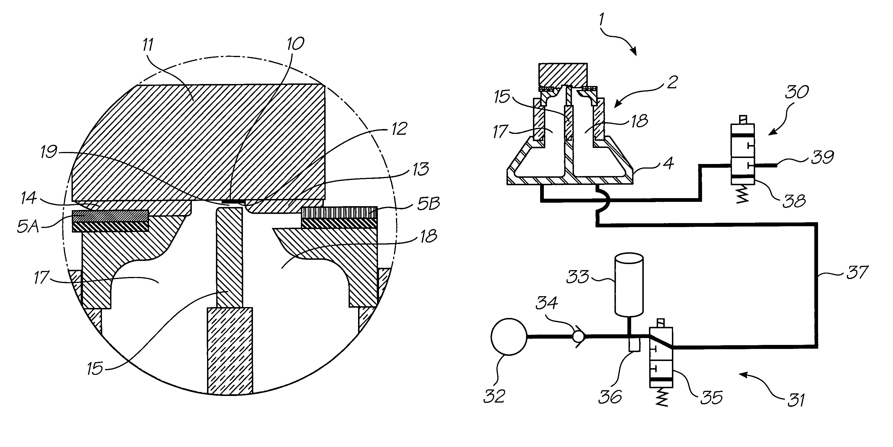
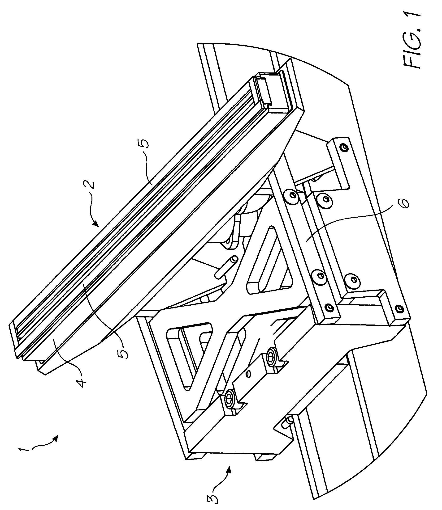
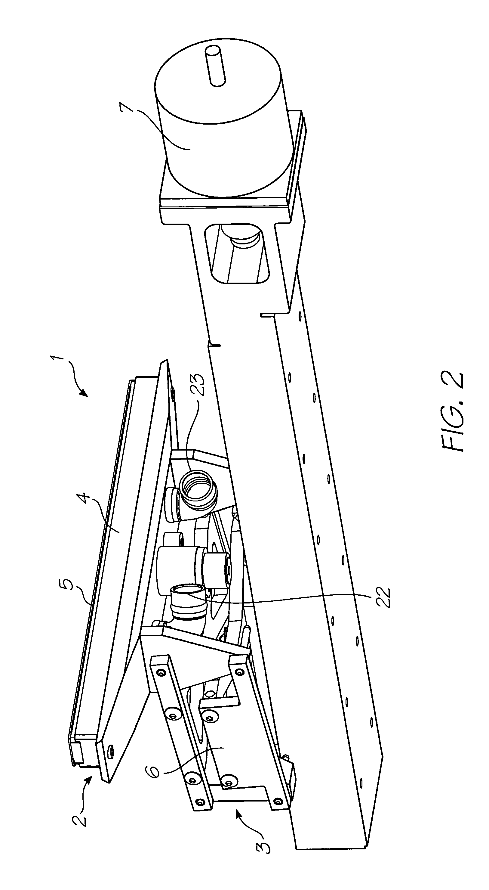
[0115]Referring to FIGS. 1 and 2, there is shown part of a printhead maintenance station 1 comprising a capper 2 and an engagement mechanism 3. The capper 2 takes the form of an elongate capping chamber 4 having a perimeter gasket 5 fixed around one end. The capping chamber 4 with gasket 5 is configured to fit and form a seal around a pagewidth printhead 10 (see FIGS. 3 and 4).

[0116]In the embodiment shown, the engagement mechanism 3 takes the form of a pantograph 6, which raises and lowers the capper 2 into sealing engagement and out of engagement from around the printhead 10. The pantograph 6 is actuated using a motor 7, which raises and lowers the pantograph via a cam arrangement (not shown). Other types of engagement mechanism suitable for raising and lowering the capper 2 will, of course, be readily apparent to the person skilled in the art.

[0117]Referring to FIGS. 3 and 4, the capper 2, engaged around the printhead 10, is shown in more detail. The printhead 10 is mounted on an...


PUM


Abstract

A printhead maintenance assembly is provided, comprising a printhead and a maintenance station. The maintenance station comprises a capper sealingly engageable around the printhead. The capper includes a constriction member for defining a blast channel adjacent an ink ejection face of the printhead. The maintenance station also comprises a vacuum system in fluid communication with the capper and an engagement mechanism. The engagement mechanism is provided for moving the capper between a first position in which the capper is sealingly engaged around the printhead and a second position in which the capper is disengaged from around the printhead.

Description

FIELD OF THE INVENTION[0001]This invention relates to a printhead maintenance assembly for an inkjet printhead. It has been developed primarily for facilitating maintenance operations, such as cleaning particulates from an ink ejection face of the printhead.[0002]Co-Pending Applications[0003]The following applications have been filed by the Applicant simultaneously with the present application:[0004]11 / 24667611 / 24667711 / 24667811 / 24667911 / 24668011 / 24668111 / 24671411 / 24671311 / 24668911 / 24667111 / 24667011 / 24666911 / 24670411 / 24671011 / 24668811 / 24671611 / 24671511 / 24670711 / 24670611 / 24670511 / 24670811 / 24669311 / 24669211 / 24669611 / 24669411 / 24668711 / 246718732268111 / 24668611 / 24670311 / 24669111 / 24671111 / 24669011 / 24671211 / 24671711 / 24670911 / 24670011 / 24670111 / 24670211 / 24666811 / 24669711 / 24669811 / 24669911 / 24667511 / 24667411 / 246667730393011 / 24667211 / 24667311 / 24668311 / 246682[0005]The disclosures of these co-pending applications are incorporated herein by reference.Cross References to Related Applications[0006]V...

Claims


Application Information

Patent Timeline
Patent Type & Authority Patents(United States)
IPC IPC(8): B41J2/165
CPCB41J2/16508
Inventor KARPPINEN, VESASILVERBROOK, KIA
Owner SILVERBROOK RES PTY LTD
Why Eureka
Try Eureka